Hello, good evening everyone~
Today we have another technical article about Siemens communication!
Siemens Modbus RTU Communication:
S7-200 Smart Modbus RTU Master Station Communication (√)
S7-200 Smart Modbus RTU Slave Station Communication (√)
RS485/232 Communication Ports and DP Connector Connection Methods (√)
S7-1200 Modbus (RTU) Instruction V3 Basic Functions
S7-1200 Modbus (RTU) Instruction V4 New Functions
RS485 Repeater
Can be used to extend network distance, electrically isolate different network segments, and increase the number of communication nodes. The functions of the repeater are as follows:
1. Extend Network Distance:
Adding a repeater to the network allows for an extension of 50m. If two repeaters are connected together without other nodes in between, the network can be extended by 1000m. A maximum of 9 Siemens repeaters can be used in one network. As shown in Figure 1-1, using an RS485 repeater to extend the network.
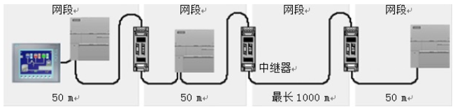 Figure 1-1 Using RS485 Repeater to Extend Network
Note:1. When using S7-200 SMART CPU free port communication, Modbus RTU communication, and USS communication, Siemens repeaters cannot be used to extend the network.
2. Electrical Isolation of Different Network Segments:
Isolating networks can ensure that network segments with different reference point potentials are isolated from each other, thus ensuring communication transmission quality.
3. Increase Network Devices:
A maximum of 32 communication nodes can be connected in one RS485 network segment. Using a repeater can extend a network segment, allowing for an additional 32 communication nodes. However, the repeater itself occupies one communication node position, so the extended segment can only connect to 31 additional communication nodes.
RS485 Network Connector
Siemens provides two types of RS485 network connectors (as shown in 1-2 RS485 Network Connector), which can easily connect multiple communication nodes to the communication network. One is the standard network connector, while the other has a programmable interface. The network connector with a programmable interface can extend all communication pins of the RS485 port integrated into the S7-200 SMART CPU to the programming interface, where pins 2 and 7 provide 24VDC power for connecting TD400C.
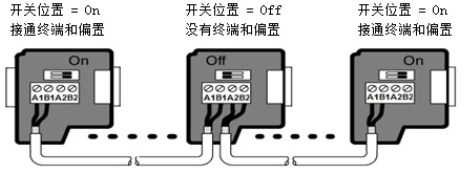
Figure 1-2 RS485 Network Connector
The network connector has two sets of connection terminals for connecting input and output cables. The network connector has a selection switch for terminal and bias resistors. Communication nodes at both ends of the network must set the selection switch of the network connector to On, while communication nodes in the middle of the network need to set the selection switch to Off. The typical wiring for terminal and bias resistors of the network connector is shown in Table 1.
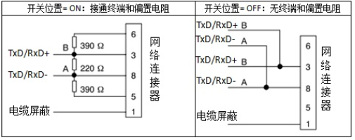
Table 1 Network Connector Terminal and Bias Resistor
Using the SBCM01 signal board can be used to connect to the RS485 network. When the signal board is a terminal communication node, terminal resistors and bias resistors need to be connected, as shown in the typical circuit diagram in Figure 1-3 SBCM01 Signal Board Terminal and Bias Resistor Wiring Diagram.
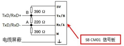
Figure 1-3 SBCM01 Signal Board Terminal and Bias Resistor Wiring
Note:
● Terminal resistors are used to eliminate signal reflections caused by discontinuities in characteristic impedance in communication cables. When the signal reaches the end of the network, if the cable impedance is very low or has no impedance, signal reflections will occur at that point. The method to eliminate such reflections is to connect a terminal resistor at both ends of the network that matches the characteristic impedance of the cable, ensuring continuity of cable impedance.
● When there are no communication nodes sending data on the network, the network bus is in an idle state. Adding bias resistors can provide a defined idle potential on the bus, ensuring the stability of logical signals “0” and “1”.
Today, I shared the article “Siemens PLC Communication – Modbus RTU Communication and RS485 Network Connection’s RS485 Repeater and RS485 Network Connector”. You can bookmark it for use. If you encounter any issues or have any questions, feel free to add me on WeChat: 18018269808 for private chat or leave a comment. If you like it, please follow me, like and share, thank you!
We take online activities seriously! Learning course packages are available at discounted prices! Helping everyone learn!






Smart Control Education Official Website: http://plc.czzkplc.com/czplc/home Free materials and courses can be viewed on the website!
You can purchase through the mini-program!

● Siemens PLC Communication – Modbus RTU Communication – RS485/232 Communication Ports and DP Connector Connection Methods
● Siemens PLC Communication – Modbus RTU Communication – S7-200 Smart Modbus RTU Slave Station Communication
● Siemens PLC Communication – 200 Smart and 1200 PLC S7 Communication
● Common Instructions in Boto: EIXT Immediate Exit Loop
● Common Instructions in Boto: How to Use WHILE..DO Loop Instruction?
● Common Instructions: FOR TO DO Tutorial on Defining Loop Count
● Super Practical!! Creating Multiple Branches with CASE…OF Instruction in Boto