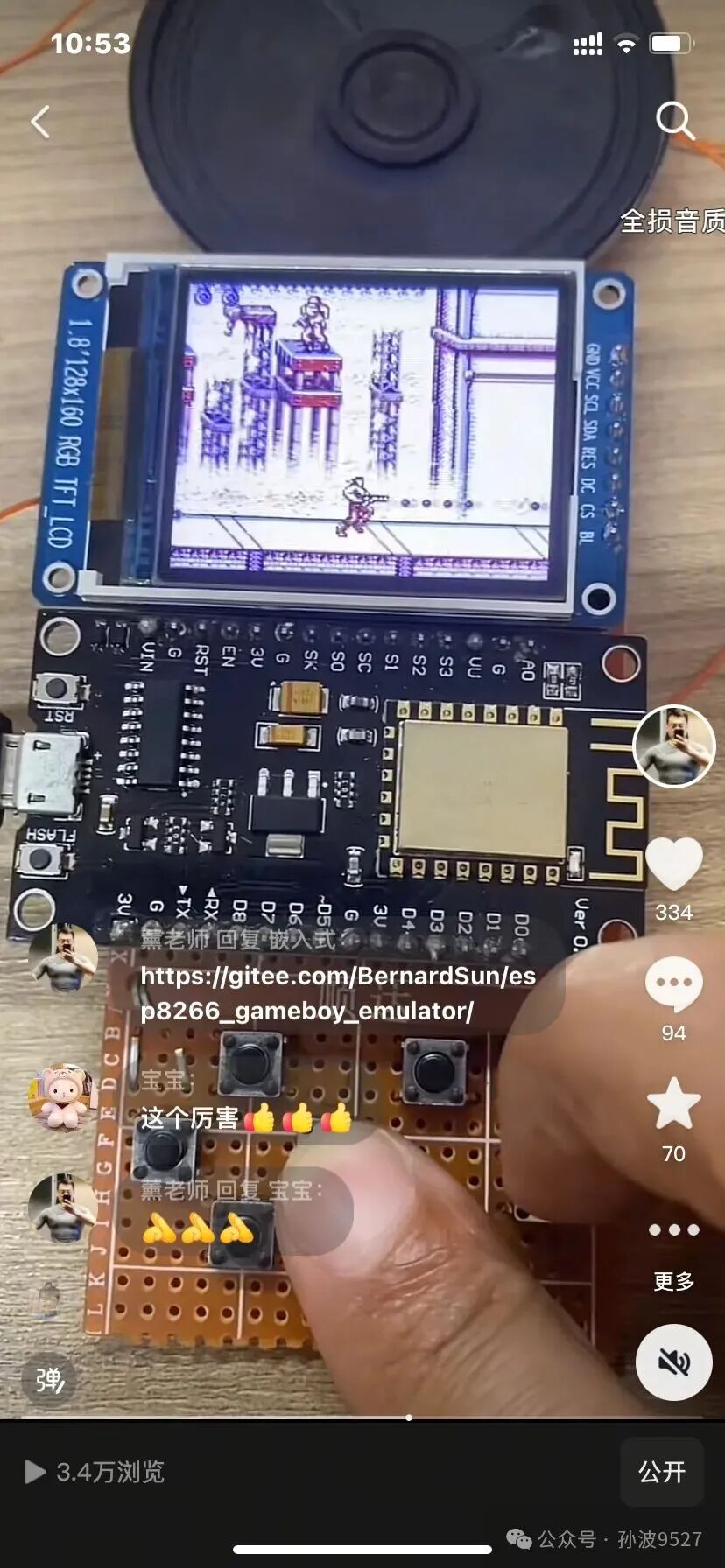
The Game Boy emulator running on the ESP8266 is part of a project from ESPboy.
https://github.com/ESPboy-edu/ESPboy_GameBoy
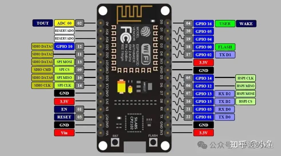
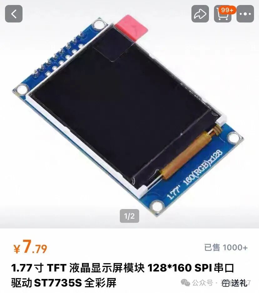
ESPboy uses the ESP8266 as the processor and employs an I2C chip to expand GPIO for controlling the Game Boy, as the usable IO on the ESP8266 is quite limited. It uses an ST7735 LCD with a resolution of 128×128, and a DAC chip is used to control the brightness of the LCD.
I have made some simplifications and modifications:
1. I tried to use the GPIO on the ESP8266 for controlling buttons, eliminating the keyboard expansion chip. For insufficient GPIO, I used an ADC to read a voltage divider circuit. It is important to note that buttons that need to be used together cannot be on the same ADC interface, as the ESP8266 only has one ADC interface. The LCD uses three, audio uses one, and D0, 6, or 8 cannot be used for some unknown reason. It is indeed quite limiting.
2. I used a 160×128 LCD because the Game Boy’s resolution is 160×144. Although 16 rows cannot be displayed, it does not affect gameplay and looks much better. I eliminated the brightness control chip and connected it directly to the power supply.
3. I removed the original LED flashing lights and logo display to save flash space.
Approximate wiring:
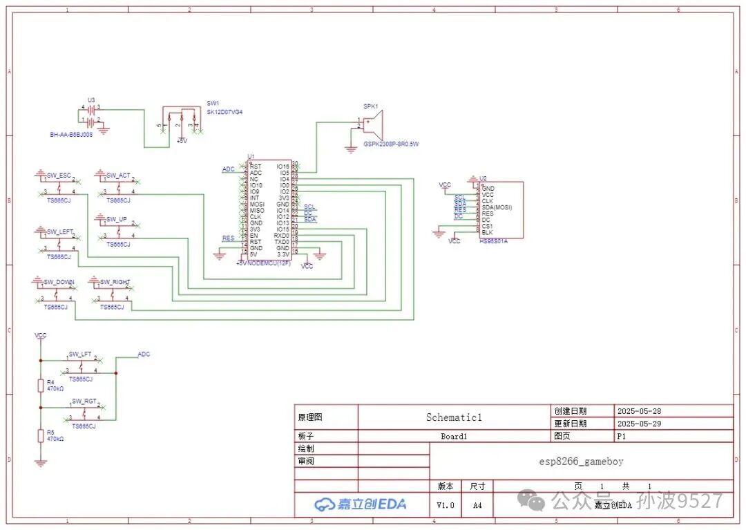
There are still a couple of bugs in the circuit diagram, which I will address in subsequent articles.