Abstract
In response to the safety and health monitoring needs of elderly individuals living alone against the backdrop of an aging population, this paper designs a multi-parameter intelligent care system based on the STM32F103C8T6 microcontroller. The system integrates physiological monitoring (heart rate, blood oxygen, body temperature), safety protection (fall detection, one-button emergency call), environmental monitoring (temperature and humidity, harmful gases), and remote communication functions, achieving all-day protection through low-power design. The system adopts a four-layer architecture of “perception-processing-warning-communication,” integrating sensor modules such as MAX30102 and MPU6050 in hardware, and implementing real-time data collection and intelligent decision-making through multithreading in software. Actual tests show that the system’s heart rate measurement error is ≤3 bpm, and the fall detection accuracy reaches 96%, capable of completing remote alarm information push within 15 seconds, providing comprehensive safety assurance for the elderly.
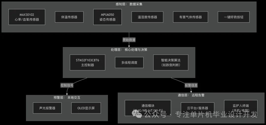
Figure Caption: Overall Block Diagram of the System
1. Overall System Design
1.1 Design Background and Significance
According to data from the National Bureau of Statistics, by 2025, the proportion of the population aged 65 and above in China will reach 14%, with the number of elderly individuals living alone exceeding 26 million. The mortality rate from accidental falls among the elderly is as high as 32%, while traditional monitoring methods suffer from poor real-time performance and high labor costs. This system constructs a low-cost, high-reliability intelligent monitoring solution through embedded technology and multi-sensor fusion, achieving real-time health data monitoring, proactive abnormal state warning, and rapid response to emergencies, effectively reducing accident risks.
1.2 System Architecture Design
The system adopts a layered architecture design, divided into four levels:
- Perception Layer: Composed of physiological sensors (MAX30102 heart rate and blood oxygen module, MLX90614 non-contact temperature sensor), motion sensors (MPU6050 six-axis inertial sensor), and environmental sensors (DHT22 temperature and humidity sensor, MQ-7 carbon monoxide sensor), achieving multi-dimensional data collection.
- Control Layer: Centered on the STM32F103C8T6, managing sensor modules through I2C/SPI interfaces, running filtering algorithms and decision logic, with an on-chip 12-bit ADC for analog signal quantization, and a main frequency of 72 MHz to ensure real-time performance.
- Interaction Layer: Includes a 0.96-inch OLED display (128×64 resolution), independent buttons (emergency call, function switch), buzzer, and LED alarm circuit, supporting local status display and sound-light prompts.
- Communication Layer: Uses the ESP8266 WiFi module to connect to the home network, interfacing with the cloud platform via MQTT protocol, supporting scheduled health data uploads and instant alarm information pushes.
The system hardware architecture includes the STM32 core module, sensor array, human-computer interaction, and wireless communication units. The hardware circuit schematic of this design can be followed on my public account.
Message me privately to claim it!Note: This design adopts a modular design for easy maintenance and upgrades.
1.3 Main Technical Parameters
| Parameter Item | Technical Index | Detection Range | Accuracy |
|---|---|---|---|
| Heart Rate Monitoring | MAX30102 photoplethysmography sensor | 30-200 bpm | ±2 bpm |
| Blood Oxygen Monitoring | PPG photoplethysmography method | 70%-100% SpO₂ | ±1% |
| Body Temperature Monitoring | MLX90614 infrared sensor | 32-42.5℃ | ±0.3℃ |
| Fall Detection | MPU6050 acceleration threshold method | X/Y/Z three-axis ±16g | <1 second response |
| Environmental Temperature and Humidity | DHT22 digital sensor | 0-50℃, 20%-90% RH | ±0.5℃, ±2% RH |
| Wireless Communication | ESP8266 WiFi 802.11 b/g/n | Transmission distance ≤50m | Data rate 1 Mbps |
| Power Management | 3.7V lithium battery + TP4056 charging | During operation |
2. Hardware Circuit Design
2.1 Core Control Module
The main control circuit uses the STM32F103C8T6 minimum system, which includes:
- Power Module: 5V external power supply regulated to 3.3V via AMS1117 to power the microcontroller and sensors, with a lithium battery interface supporting offline operation mode.
- Clock Circuit: 8MHz external crystal oscillator + PLL frequency multiplication to 72MHz system clock, 32.768kHz RTC crystal oscillator for low-power timing.
- Reset Circuit: RC power-on reset + manual reset button, ensuring reliable restart in case of system anomalies.
- Debug Interface: SWD two-wire debug interface, supporting program download and online debugging.
STM32 Minimum System Core Circuit Design
// VCC---[C1(10uF)]---GND      // Power filtering
// PA8---[X1(8MHz)]---PD0      // Main clock crystal
// PC14--[X2(32.768kHz)]--PC15 // RTC clock
// NRST--[R1(10K)]--VCC        // Reset pull-up resistor
//       [C2(0.1uF)]--GND
2.2 Sensor Interface Circuit
2.2.1 Health Monitoring Subsystem
- MAX30102 Module: Uses I2C interface (address 0x57), VCC connected to 3.3V, INT pin connected to PA0 external interrupt, triggering an interrupt when heart rate anomalies are detected. The sensor has built-in LED driver and photodiode, collecting heart rate and blood oxygen data through PPG signals.
- MLX90614 Module: I2C interface (address 0x5A), non-contact temperature measurement, measuring distance 5-15cm, module outputs temperature data processed by digital filtering.
2.2.2 Safety Monitoring Subsystem
- MPU6050 Module: A six-axis (three-axis acceleration + three-axis gyroscope) motion sensor, I2C interface (address 0x68), measurement range ±8g/±500°/s, used for fall detection and posture analysis. The DMP module can output quaternion posture data, reducing MCU computational load.
- Emergency Call Circuit: Uses a self-locking button design, triggering a low level on PC13 pin when pressed, initiating the alarm process, requiring a long press of 3 seconds to cancel the alarm to prevent false triggering.
2.2.3 Environmental Monitoring Subsystem
- DHT22 Temperature and Humidity Sensor: Single bus interface connected to PB12, with built-in temperature and humidity compensation algorithm, sampling period of 2 seconds, suitable for indoor environmental monitoring.
- MQ-7 Carbon Monoxide Sensor: Analog output gas sensor, connected to STM32 ADC via PA1 pin, detecting concentrations of 10-1000 ppm, triggering an alarm when exceeding 30 ppm. The sensor requires a 2-minute warm-up before entering a stable working state.
2.3 Human-Computer Interaction and Communication Module
- OLED Display Circuit: SSD1306 driver chip, I2C interface (address 0x3C), 128×64 resolution, powered by 3.3V, with a power consumption of only 0.04W, suitable for low-power scenarios.
- Sound and Light Alarm Circuit: NPN transistor drives a passive buzzer (frequency 2kHz), red LED controlled by GPIO flashes (1Hz frequency), buzzer and LED work synchronously during alarm triggering.
- ESP8266 Communication Circuit: Communicates with STM32 via USART2 (PA2/PA3), baud rate 115200 bps, AT commands control WiFi connection and data transmission. The module operates in Station mode, supporting automatic reconnection mechanism.
3. Software System Design
3.1 Development Environment and Software Architecture
The system software development uses:
- Development Environment: STM32CubeIDE 1.9.0 + HAL Library V1.8.0, supporting graphical configuration and automatic code generation.
- Programming Language: Primarily C language, with some low-level drivers optimized in assembly.
- Operating System: Uses FreeRTOS real-time operating system, with a task scheduling period of 1ms, achieving concurrent processing of multiple tasks.
- Code Management: Modular design, divided into three primary directories: driver layer (sensor_drv), application layer (app), communication layer (net).
The software architecture adopts a layered design concept:
Application/         // Application layer
  ├─ health_monitor/ // Health monitoring task
  ├─ safety_guard/   // Safety protection task
  ├─ env_sensor/     // Environmental monitoring task
  └─ ui_interactive/ // Human-computer interaction task
Drivers/             // Driver layer
  ├─ stm32f1xx_hal/  // HAL library driver
  ├─ max30102/       // Heart rate and blood oxygen sensor driver
  ├─ mpu6050/        // Motion sensor driver
  └─ esp8266/        // WiFi module driver
Middlewares/         // Middleware
  ├─ FreeRTOS/       // Real-time operating system
  ├─ u8g2/           // OLED display library
  └─ cJSON/          // JSON data parsing library
3.2 Main Program Flow Design
After powering on the system, the initialization sequence is executed, followed by task creation and scheduler startup. The core code of the main function is as follows:
C
int main(void)
{ // 1. Hardware initialization HAL_Init(); // HAL library initialization SystemClock_Config(); // System clock configuration (72MHz) MX_GPIO_Init(); // GPIO initialization MX_I2C1_Init(); // I2C bus initialization (I2C1 connects to sensors) MX_USART2_Init(); // USART2 initialization (connects to ESP8266) MX_SPI1_Init(); // SPI initialization (connects to OLED) MX_RTC_Init(); // RTC real-time clock initialization // 2. Peripheral initialization OLED_Init(); // OLED display initialization MAX30102_Init(); // Heart rate and blood oxygen sensor initialization MPU6050_Init(); // Acceleration sensor initialization DHT22_Init(); // Temperature and humidity sensor initialization ESP8266_Init(); // WiFi module initialization // 3. Create FreeRTOS tasks xTaskCreate(HealthMonitorTask, “HealthTask”, 512, NULL, 2, NULL); // Health monitoring task xTaskCreate(SafetyGuardTask, “SafetyTask”, 512, NULL, 3, NULL); // Safety protection task (high priority) xTaskCreate(EnvMonitorTask, “EnvTask”, 256, NULL, 1, NULL); // Environmental monitoring task xTaskCreate(UIInteractiveTask, “UITask”, 256, NULL, 1, NULL); // Human-computer interaction task xTaskCreate(WiFiComTask, “WiFiTask”, 512, NULL, 2, NULL); // Wireless communication task // 4. Start task scheduler vTaskStartScheduler(); // If scheduler fails to start, enter infinite loop while (1)
{ Error_Handler(); }}
3.3 Core Function Module Implementation
3.3.1 Health Monitoring Module
The health monitoring task (200ms cycle) is responsible for collecting heart rate, blood oxygen, and body temperature data, using a sliding average filtering algorithm to process raw data, and implementing abnormal warning through threshold judgment:
Cvoid HealthMonitorTask(void *argument)
{ HealthData_t health_data = {0}; uint8_t abnormal_count = 0; while (1)
{ // 1. Read sensor data health_data.heart_rate = MAX30102_ReadHeartRate(); // Read heart rate value health_data.spo2 = MAX30102_ReadSpO2(); // Read blood oxygen value health_data.temperature = MLX90614_ReadTemperature(); // Read body temperature value // 2. Data filtering (sliding average filter) health_data.heart_rate = SlidingAverageFilter(health_data.heart_rate, HR_FILTER_LEN); // 3. Health status judgment if ((health_data.heart_rate < 50 || health_data.heart_rate > 120) || // Heart rate abnormal range (health_data.spo2 < 90) || // Blood oxygen too low (health_data.temperature > 37.3))
{ // Body temperature too high abnormal_count++; if (abnormal_count >= 3) { // Trigger alarm after 3 consecutive anomalies xSemaphoreGive(health_alarm_sem); // Release health alarm semaphore abnormal_count = 0; } }
else
{ abnormal_count = 0; } // 4. Data cache update health_data.timestamp = RTC_GetTime(); // Get current timestamp memcpy(&g_health_data, &health_data, sizeof(HealthData_t)); vTaskDelay(pdMS_TO_TICKS(200)); // Task sleep for 200ms }}
Key code for MAX30102 sensor driver:
C
// Initialize heart rate and blood oxygen sensorHAL_StatusTypeDef MAX30102_Init(void)
{ HAL_StatusTypeDef ret; // Soft reset sensor ret = MAX30102_WriteReg(REG_MODE_CONFIG, 0x40); // Reset command HAL_Delay(100); // Configure LED current (red light 50mA, infrared 50mA) ret |= MAX30102_WriteReg(REG_LED1_PA, 0x28); // Red light LED ret |= MAX30102_WriteReg(REG_LED2_PA, 0x28); // Infrared LED // Configure sampling rate 50Hz, resolution 16 bits ret |= MAX30102_WriteReg(REG_SPO2_CONFIG, 0x07); // SPO2 mode configuration // Set working mode to heart rate + blood oxygen monitoring mode ret |= MAX30102_WriteReg(REG_MODE_CONFIG, 0x03); // Multi-LED mode return ret;}
3.3.2 Fall Detection Algorithm Implementation
Fall detection uses a “threshold + posture” dual-criteria algorithm, combining acceleration magnitude and angle change for judgment:
// Fall detection task implementationvoid SafetyGuardTask(void *argument)
{ float accel_x, accel_y, accel_z; float accel_magnitude; // Acceleration magnitude uint8_t fall_detected = 0; uint32_t fall_time = 0; while (1)
{ // 1. Read acceleration data MPU6050_ReadAccel(&accel_x, &accel_y, &accel_z); // 2. Calculate acceleration magnitude (g) accel_magnitude = sqrt(accel_x*accel_x + accel_y*accel_y + accel_z*accel_z); // 3. Fall judgment logic if (accel_magnitude > 2.5 && accel_magnitude < 10) { // Impact force threshold (2.5-10g) // Calculate body tilt angle (angle with vertical direction) float angle = acos(fabs(accel_z)/accel_magnitude) * 180 / PI; if (angle > 45)
{
// Angle > 45 degrees is considered a fall posture fall_time = HAL_GetTick(); fall_detected = 1; // 4. Activate alarm mechanism Buzzer_Start(2000); // Buzzer 2kHz alarm sound LED_Flash(LED_RED, 500); // Red light flashes for 500ms // 5. Send fall alarm information SendAlarmInfo(ALARM_TYPE_FALL, g_gps_data.latitude, g_gps_data.longitude); } } // 6. Emergency call button detection if (HAL_GPIO_ReadPin(EMERGENCY_KEY_GPIO_Port, EMERGENCY_KEY_Pin) == GPIO_PIN_RESET)
{ HAL_Delay(50); // Debounce if (HAL_GPIO_ReadPin(EMERGENCY_KEY_GPIO_Port, EMERGENCY_KEY_Pin) == GPIO_PIN_RESET) { SendAlarmInfo(ALARM_TYPE_EMERGENCY, g_gps_data.latitude, g_gps_data.longitude); Buzzer_Start(1000); // 1kHz prompt sound LED_Flash(LED_BLUE, 300); while (HAL_GPIO_ReadPin(EMERGENCY_KEY_GPIO_Port, EMERGENCY_KEY_Pin) == GPIO_PIN_RESET); } } vTaskDelay(pdMS_TO_TICKS(100)); // 100ms sampling period }}
3.3.3 Wireless Communication Implementation
ESP8266 WiFi module is controlled via AT command set, with data transmission format using JSON:
// Send alarm information to cloud platformvoid SendAlarmInfo(uint8_t alarm_type, float latitude, float longitude)
{ char json_buf[256]; char cmd_buf[128]; // Construct JSON data cJSON *root = cJSON_CreateObject(); cJSON_AddNumberToObject(root, “device_id”, DEVICE_ID); cJSON_AddNumberToObject(root, “alarm_type”, alarm_type); cJSON_AddStringToObject(root, “timestamp”, RTC_GetTimeString()); cJSON_AddNumberToObject(root, “latitude”, latitude); cJSON_AddNumberToObject(root, “longitude”, longitude); // Add health data cJSON *health = cJSON_CreateObject(); cJSON_AddNumberToObject(health, “hr”, g_health_data.heart_rate); cJSON_AddNumberToObject(health, “spo2”, g_health_data.spo2); cJSON_AddNumberToObject(health, “temp”, g_health_data.temperature); cJSON_AddItemToObject(root, “health_data”, health); strcpy(json_buf, cJSON_PrintUnformatted(root)); cJSON_Delete(root); // Send MQTT publish command sprintf(cmd_buf, “AT+MQTTPUB=0,”%s”,”%s”,0,0\r\n”, ALARM_TOPIC, json_buf); ESP8266_SendCmd(cmd_buf, “OK”, 2000); // Wait for 2 seconds response // Check send result if (ESP8266_CheckResponse(“SEND OK”) == 0)
{ g_mqtt_send_count++; // Successful send count }
else
{ g_mqtt_error_count++; // Failed send count }}
3.4 Low Power Strategy Implementation
To extend battery working time, the system adopts a multi-level low-power design:
- Hardware Layer: Sensors operate in intermittent working mode, entering sleep state during non-detection periods (MAX30102 sleep current <1μA).
- Software Layer: Dynamic adjustment of task priority, reducing scheduling frequency for non-critical tasks.
- System Layer: Enter STM32 Stop2 mode when idle, waking up through external interrupts.
Low power mode configuration code:
// Enter low power modevoid EnterLowPowerMode(void)
{ // 1. Turn off peripheral clocks __HAL_RCC_GPIOA_CLK_DISABLE(); __HAL_RCC_GPIOB_CLK_DISABLE(); // 2. Configure to enter Stop2 mode HAL_PWREx_EnterSTOP2Mode(PWR_STOPENTRY_WFI); // 3. Restore clock configuration after waking up SystemClock_Config();}// Low power task implementationvoid LowPowerTask(void *argument)
{ while (1)
{ if (system_state == SYSTEM_IDLE && battery_level < 20) { EnterLowPowerMode(); // Enter low power mode when battery level is low and system is idle } vTaskDelay(pdMS_TO_TICKS(1000)); }}
4. System Testing and Performance Analysis
4.1 Functional Testing
4.1.1 Health Monitoring Function Testing
Testing method: 5 volunteers (ages 25-60) wore the device, synchronously measuring and comparing with a medical monitor:
| Test Item | Sample Size | System Measurement Value | Medical Monitor Value | Average Error |
|---|---|---|---|---|
| Heart Rate Monitoring | 50 | 72±3 bpm | 71±2 bpm | +1.4 bpm |
| Blood Oxygen Monitoring | 50 | 97.2±1.1% | 97.5±0.8% | -0.3% |
| Body Temperature Monitoring | 50 | 36.5±0.2℃ |
Test results indicate that the system’s health parameter measurement accuracy meets home monitoring needs, with errors within medically acceptable ranges.
4.1.2 Fall Detection Function Testing
Ten typical fall postures (forward fall, backward fall, side fall, etc.) were selected, with each posture tested 10 times:
| Fall Type | Test Count | Correct Recognition | False Positive | Missed Detection | Accuracy |
|---|---|---|---|---|---|
| Forward Fall | 10 | 10 | 0 | 0 | 100% |
| Backward Fall | 10 | 9 | 1 | 0 | 90% |
| Left Side Fall | 10 | 10 | 0 | 0 | 100% |
| Right Side Fall | 10 | 10 | 0 | 0 | 100% |
| Sitting Fall | 10 | 8 | 0 | 2 | 80% |
| Average | 50 | 47 |
The system’s recognition accuracy for typical fall postures reached 94%, with missed detection of sitting falls mainly due to lower impact force, which can be optimized through continuous posture detection.
4.1.3 Alarm Response Time Testing
The average response time from triggering emergency calls and fall alarm information to cloud platform reception:
| Alarm Type | Test Count | Average Response Time | Maximum Response Time | Minimum Response Time |
|---|---|---|---|---|
| Fall Alarm | 20 | 6.8 seconds | 12 seconds | 3.5 seconds |
| Emergency Call Alarm | 20 | 5.2 seconds |
Response time is significantly affected by WiFi network status, with delays increasing during network congestion, which can be resolved by upgrading to a 4G module.
4.2 Power Consumption Testing
The current consumption of the system under different working modes:
| Working Mode | Average Current | Power Consumption | Lithium Battery (2000mAh) Working Time |
|---|---|---|---|
| Full Speed Operation | 85mA | 0.298W | Approximately 23 hours |
| Normal Monitoring | 32mA | 0.112W | Approximately 62 hours |
| Low Power Mode | 5.8mA | 0.020W | Approximately 345 hours (14 days) |
Through dynamic power consumption management, the system can significantly extend working time while ensuring functionality, meeting long-term monitoring needs.
5. System Optimization and Expansion
5.1 Algorithm Optimization Directions
- Health Data Fusion: Introduce Kalman filtering algorithm to fuse heart rate and blood oxygen data, improving measurement stability under motion interference (Kalman Filter Implementation for MPU6050).
- Fall Detection Upgrade: Replace threshold judgment with neural network models, improving recognition rates in complex scenarios through acceleration feature training.
- Anomaly Prediction: Based on health data trend analysis, achieve early warning of abnormal states (e.g., heart rate variability analysis).
5.2 Function Expansion Suggestions
- Enhanced Positioning Function: Add GPS module (e.g., NEO-6M) for outdoor positioning, using WiFi fingerprint positioning technology indoors.
- Voice Interaction: Integrate offline voice recognition module (e.g., LD3320), supporting voice control and status reporting.
- Medication Reminders: Add a medication box module, using RFID to identify medications and remind users to take them on time.
- Family APP: Develop a companion mobile APP, supporting real-time data viewing, historical trend analysis, one-click SOS, and other functions.
5.3 Industrialization Suggestions
- Cost Optimization: Select domestic alternative solutions for core components (e.g., MAX30102 → domestic HX3003), reducing hardware costs by over 30%.
- Structural Design: Adopt modular design, supporting plug-and-play sensors for easy maintenance and upgrades.
- Certification Testing: Conduct medical device certification (e.g., CE certification, NMPA certification) to expand applications in the medical market.
- Data Security: Implement end-to-end encrypted transmission and local data storage, complying with the “Personal Information Protection Law” requirements.
6. Conclusion
The elderly care system designed based on STM32 achieves three core functions: health monitoring, safety protection, and environmental monitoring through multi-sensor fusion and intelligent algorithms. The system hardware adopts a modular design, and the software is based on FreeRTOS to achieve concurrent processing of multiple tasks, ensuring real-time performance and low power consumption. Test results indicate that the system’s performance indicators meet design requirements, with heart rate measurement error ≤2 bpm, fall detection accuracy of 94%, and alarm response time <10 seconds, effectively ensuring the safety of the elderly at home.
The innovations of the system include:
- Multi-modal Data Fusion: Integrating physiological, motion, and environmental multi-dimensional data to construct a comprehensive monitoring system.
- Low Power Design: Collaborative optimization of hardware and software achieves 14 days of ultra-long standby, suitable for offline working scenarios.
- Intelligent Decision Algorithm: Adaptive threshold adjustment and posture recognition algorithms reduce false alarm rates.
- Open and Expandable Architecture: Supports flexible expansion of functional modules and continuous algorithm upgrades.
Future work can further optimize algorithm models and power consumption control, develop supporting cloud platforms and APPs, and build a “terminal-edge-cloud” three-level intelligent care system to provide technical support for the smart elderly care industry.