Configuring and utilizing the SiemensS7-1200 PLC and simplified series panels (such as KTP400 Basic) requires a systematic approach.
1. Software Preparation
Install TIAPortal: Use version V13 or higher, ensuring it includes STEP7Basic (PLC programming) and WinCCBasic (HMI configuration) components.
Activate License: Activate the required license through AutomationLicenseManager to avoid functional limitations.
2. Create Project
Create New Project: Open TIAPortal, select “Create New Project” and name it.
Add Device:
PLC: Right-click to add a new device in the “Project Tree”, selecting a specific model from the S7-1200 series (e.g., CPU1214C).
HMI: Again, add a device, selecting the corresponding simplified panel model (e.g., KTP400 Basic).
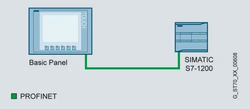
3. Network and Communication Configuration
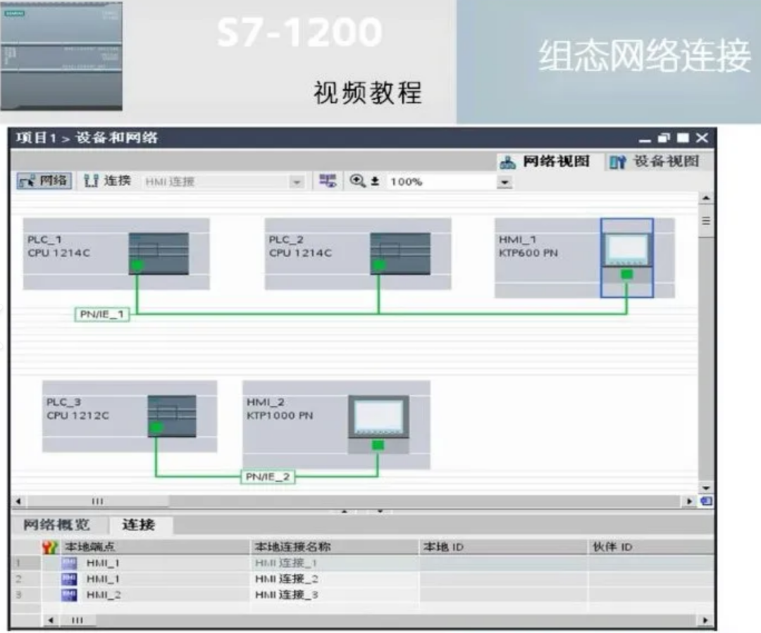
Configure Profinet Connection:
In the “Network View”, drag the HMI device to the PLC Profinet interface to automatically establish a connection.
Set IP Address: Ensure that the PLC and HMI are on the same subnet (e.g., PLC:192.168.0.1, HMI:192.168.0.2).
Verify Connection: Use the “Online and Diagnostics” feature to check the physical connection status.
4. Variable Management
PLC Variable Table: Define variables in the PLC project (e.g., “Motor_Start” corresponding to Q0.0).
HMI Variable Connection: In the HMI “Variable Table”, select “Connect” to PLC and bind the same variable name.
5. HMI Interface Design
Screen Elements:
Button: Drag the “Button” onto the screen, binding the “Motor_Start” variable in the properties, setting the pressed/ released actions.
Indicator Light: Add a circular element, binding the “Motor_Run” variable, configuring color animations (green= running, red= stopped).
Screen Navigation:
Create multiple screens (e.g., Main, Settings), using “Screen Jump” buttons to switch.
Alarm Management:
Define trigger conditions (e.g., temperature exceeding limits) in the “Alarm” tab, setting display text and priority.
6. PLC Program Design
Write Logic:
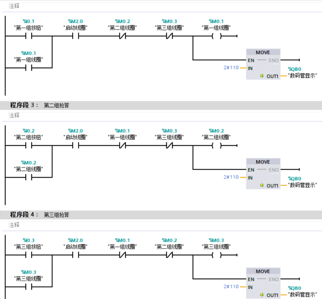
Use Ladder Diagram ( LAD) to write the start-stop circuit, linking HMI buttons and indicator light variables.
Simulation Testing: Use the PLC simulation feature of TIAPortal to validate logic without hardware.

7. Download and Debugging
Download to PLC:
Connect via Ethernet or USB/PPI cable, select “Download to Device” and confirm hardware configuration.
Download to HMI:
Use Profinet or USB cable, selecting “Transfer” mode in WinCCRuntime.
Online Testing:
Operate HMI buttons, observe PLC output point status and HMI feedback, using the “Monitoring Table” to view variable values in real-time.
8. Advanced Function Implementation
Data Logging:
Enable “Data Logging” in HMI, configuring the CSV file storage path to log key variable history.
User Permissions:
Create user groups (e.g., Operator, Engineer), set passwords, and restrict sensitive operations (e.g., parameter modifications).
Recipe Management:
Define recipes to store production parameters, with the HMI interface providing recipe selection and download functionality.
9. Troubleshooting
Communication Issues:
Check network cables, IP settings, and use the Ping command to test connectivity.
Confirm that the Profinet name (e.g., PLC_1) matches the actual device.
Variables Not Updating:
Check if the HMI variable connections point to the correct PLC, confirming that the PLC program performs read/write operations on the variables.
Screen Lag:
Reduce the number of complex graphical elements and optimize script execution frequency.
10. Maintenance and Optimization
Regular Backups: Use the “Project > Archive” feature to compress and back up the entire project.
Firmware Upgrade: Download the latest firmware from the Siemens website and update the PLC and HMI through the “Online Upgrade” in TIAPortal.
HMI Response Optimization: Enable “Asynchronous Loading” to load complex screen elements in batches.
Example Application: Motor Control System
1. HMI Interface:
Main Screen: Start/ Stop button, motor status indicator light, button to jump to parameter settings page.
Parameter Settings: Motor speed setting input box (binding to PLC “Speed_Setpoint” variable).
2. PLC Logic:
Adjust PWM output based on the HMI input of “Speed_Setpoint“, controlling the inverter through the analog module.
Detect overcurrent signals, triggering HMI alarms and logging events.