Click↑↑Technical Training, follow and pin it to subscribe for free long-term
190,000+ Industrial Control professionals follow this WeChat platform: technical sharing, learning exchange, industrial control videos
1. Requirements
Software Step7 V5.2SP1
PLC with Profibus-DP communication port: S7-315 2DP
Profibus communication cable (6XV1830-0AH10)
Profibus bus connector (6ES7972-0BB10-0XA0, with PG interface; 6ES7972-0BA10-0XA0 without PG interface)
1 MM440 inverter
Drive with Profibus communication template (6SE6400-1PB00-0AA0)
2. Configuring the Master Station System
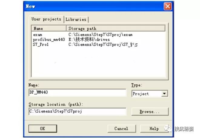
Open SIMATIC MANAGER, create a new project by selecting NEW from the FILE menu, enter the project name as DP_MM440 in the NAME field, and set the storage location below.
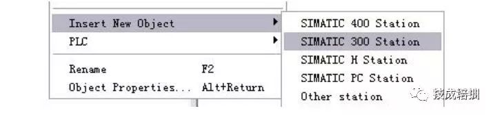
Select the project on the left side of the project screen, right-click to open the shortcut menu, and select Insert New Object to insert a SIMATIC 300 Station, and you will see the selected object appear on the right screen.
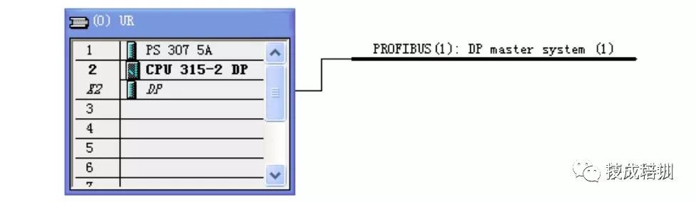
Open the SIMATIC 300 Station, then double-click the generated hardware icon on the right, go to the HWconfig that pops up for configuration, select “View” from the menu bar, select “Catalog” to open the hardware catalog, and insert the rack, power supply, and CPU in order by order number and hardware installation. When inserting the CPU, the configuration PROFIBUS screen will pop up as shown below:
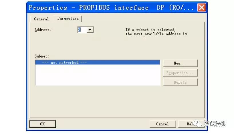
Select “New” to create a PROFIBUS (1), configure the PROFIBUS station address, click the “Properties” button to configure the network properties as shown below:
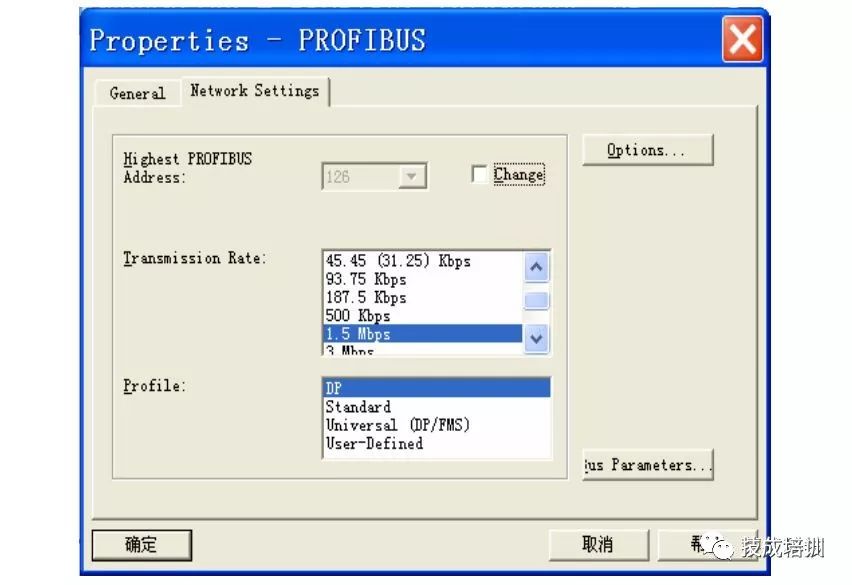
In this example, the transmission rate of the master station is “1.5Mbps”, “DP” line specification, five repeaters, OBT and other network elements. Click the “OK” button to confirm and save, then configure the S7-315 2DP local module, resulting in the following:
3. Configuring the Slave Station
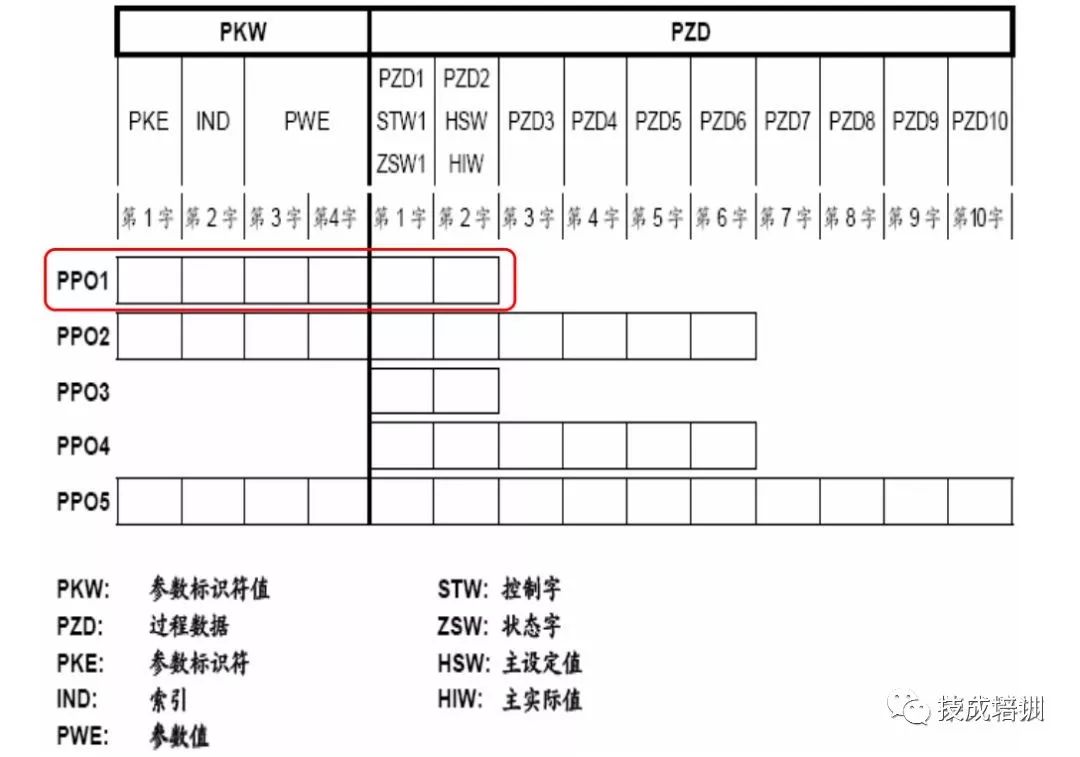
Connect the MM440 to the DP network and configure the communication area of the MM440, which is related to the application. Before configuration, confirm the type of communication PP0; in this example, PP01 is selected, consisting of 4PKW/2PZD, and MM440 only supports PP01 and PP03
Configuration steps are as follows:
A. Open the hardware configuration on the right
Profi(standard)→Profibus-DP→SIMOVERT→double-click MICROMASTER 440
B. Profibus interface Properties: Enter slave address 4
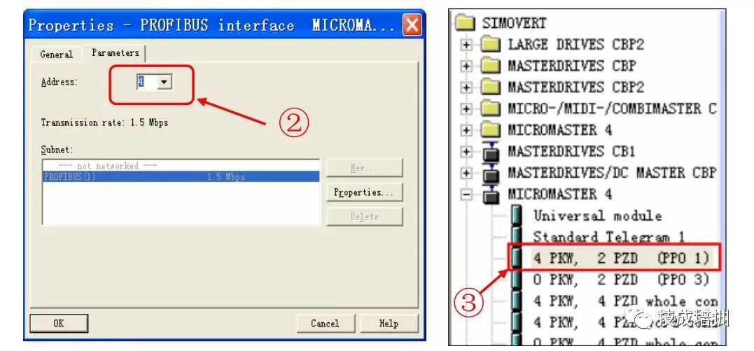
C. Select PPO type 1, double-click 4PKW/2PZD (PPO1)
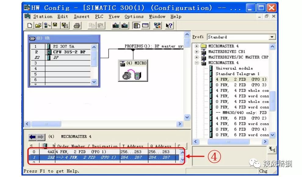
D. Slave configuration completed, address allocation from
4PKW/2PZD (256-267)
4. MM440 Hardware and Parameter Settings
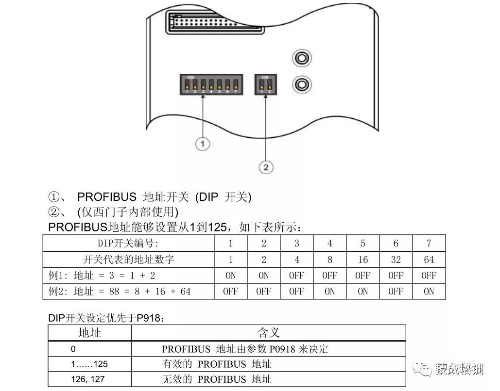
A. PROFIBUS Address
The following introduces two methods for setting the PROFIBUS bus address: using the seven DIP switches of the communication module (as shown in the figure below) or using P0918
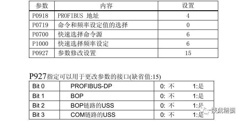
B. Communication Board Parameters
To enable the bus board to operate, the following parameters must be set:
5. Program Writing
Reading and writing PZD (Process Data)
A. Call SFC14 and SFC15 when reading and writing PZD (Process Data) parameters in Step7
B. SFC14 (DPRD_DAT) is used to read data from the Profibus slave MM440
C. SFC15 (DPRD_DAT) is used to write data to the Profibus slave MM440
D. The starting address of PZD during hardware configuration: W#16#108 (i.e., 264)
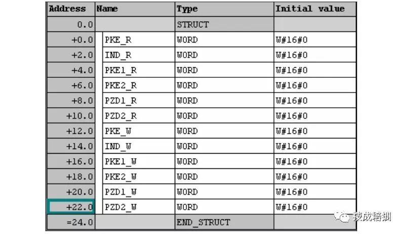
Create data block DB1
Correspond the data address in the data block with the PZD, PKW data area in the slave MM440
The data allocation in OB1 calls special function blocks SFC14 and SFC15 to complete reading and writing data from the slave MM440
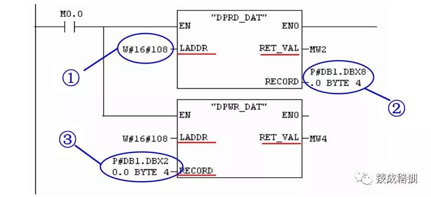
Where LADDR indicates: the starting address of PZD during recommended configuration (W#16#108 i.e., 264)
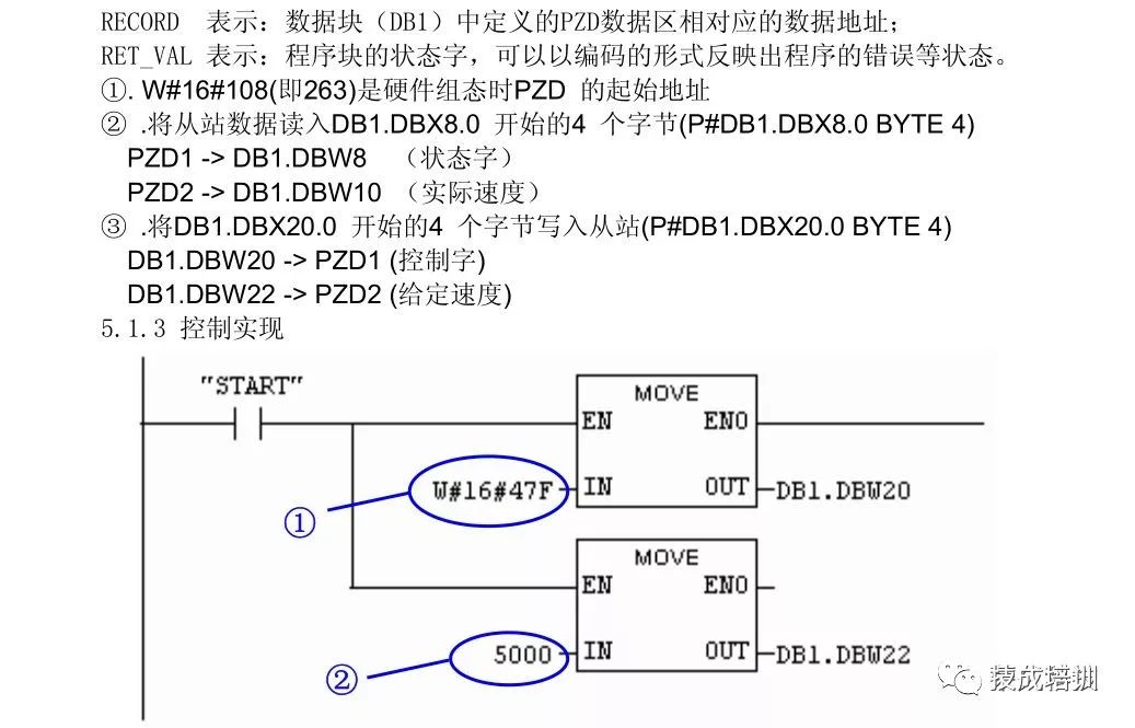
In this example, the set value and control word can be transmitted from the data block DB1, DB1.DBW20 is set to 047E then changes to 047F, the frequency value in DB1.DBW22 will output, and the status word and actual value can be read from DB1.DBW8, DB1.DBW10.
A. Control command W#16#47F, start the inverter running
B. The given speed of 5000 means 500.0 rpm.
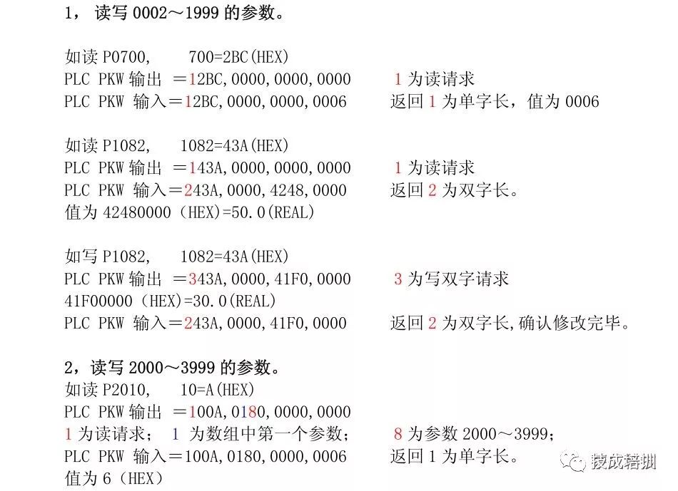
6. Reading and Writing PKW (Parameter Area)
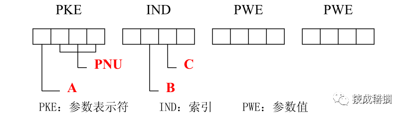
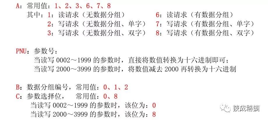
The data transmission rule for accessing PKW area data is synchronous communication, meaning that one message must be sent and a return value received before the next message can be sent. PKW generally consists of 4 sub-units, defined as follows:
Application Example
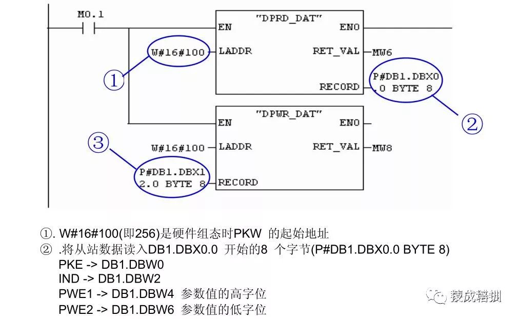
A. Call SFC14 and SFC15 when reading and writing parameters in Step7 for PKW (Parameter Area)
B. SFC14 (DPRD_DAT) is used to read data from the Profibus slave
C. SFC15 (DPRD_DAT) is used to write data to the Profibus slave
D. The starting address of PKW during hardware configuration: W#16#108 (i.e., 264)

Source: Baidu Wenku, copyright belongs to the original author, infringement will be deleted

Click↓Read the original text, for more free electrical engineering and PLC content!