Hello everyone, good evening!

Smart Control Education will officially go on holiday on February 29, 2022~ If you have any questions, you can add Xiao Zhi V: 18018269808 ; perhaps we haven’t met in person, but we have encountered each other online,Smart Control Education wishes everyone: Prosperity in 2022!
What did Smart Control experience and do in 2021? Interested friends can learn about us through this video~
Alright~ today’s tutorial is still for beginners, focusing on the TIA Portal tutorial (MODBUS TCP client with S7-1200).
MODBUS/TCP is a simple, vendor-neutral communication protocol derived from the MODBUS series for managing and controlling automation devices.
It is evident that it covers the usage of MODBUS messages in “Intranet” and “Internet” environments using TCP/IP protocol.
Next, we will mainly demonstrate the configuration of MODBUS-TCP communication.
Preparation:
1. Software version: STEP7 V13 SP1 or above
2. Firmware version: V4.1 or above for S7-1200 CPU (Currently, the TIA Portal versions available for download include V15.1, V16, and V17 has also been released, so you can use the software with confidence; for hardware, if you use V15.1, the firmware version is V4.0-V4.2, so no need to worry, and if you use V16, the firmware can go up to V4.4)
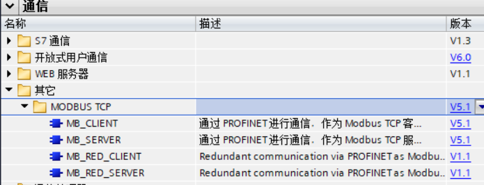 Figure 1-1

MODBUS-TCP Operating Object:
Taking communication between two S7-1200 devices as an example, we will detail how to program and communicate on the client and server sides.
|
CPU Type |
IP Address |
Port Number |
Hardware Identifier |
|
|
Client |
CPU 1214C |
192.168.0.2 |
0 |
64 |
|
Server |
CPU 1215C |
192.168.0.3 |
502 |
64 |
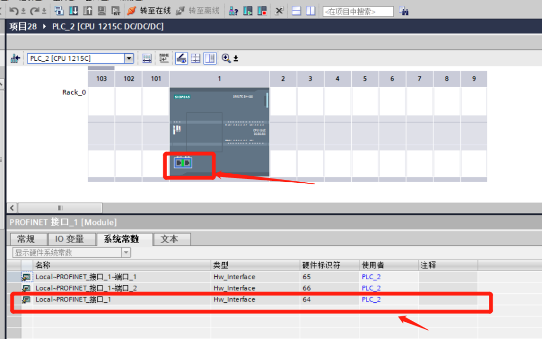 Figure 1-2
Select the interface, right-click to open properties, and check the hardware identifier in the system constants.

The S7-1200 client side needs to call the MB_CLIENT instruction block, which mainly completes the TCP connection between the client and server, sends command messages, receives responses, and controls the disconnection from the server.
Call the MB_CLIENT instruction in the program block – OB1, which will automatically generate a background DB. (Figure 1-3)
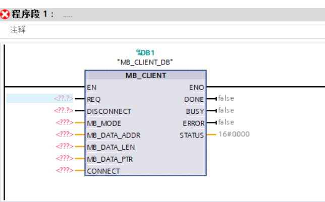 Figure 1-3
The definitions of each pin of this function block are as follows:
|
REQ |
Communication request with the server, effective on the rising edge. |
|
DISCONNECT |
This parameter can control the establishment and termination of the connection with the Modbus TCP server. 0 (default): establish connection; 1: disconnect. |
|
MB_MODE |
Select the Modbus request mode (read, write, or diagnostic). 0: read; 1: write. |
|
MB_DATA_ADDR |
The starting address of the data accessed by the “MB_CLIENT” instruction. |
|
MB_DATA_LEN |
Data length: the number of bits or words accessed. |
|
MB_DATA_PTR |
Pointer to the Modbus data register. |
|
CONNECT |
Pointer to the connection descriptor structure. TCON_IP_v4 (S7-1200) |
|
DONE |
When the last job is successfully completed, immediately set the output parameter DONE to “1”. |
|
BUSY |
Job status bit: 0: no “MB_CLIENT” job is being processed; 1: “MB_CLIENT” job is being processed. |
|
ERROR |
Error bit: 0: no error; 1: error occurred, check STATUS for the reason. |
|
STATUS |
Detailed status information of the instruction. |

First step, create a new global data block DB2:
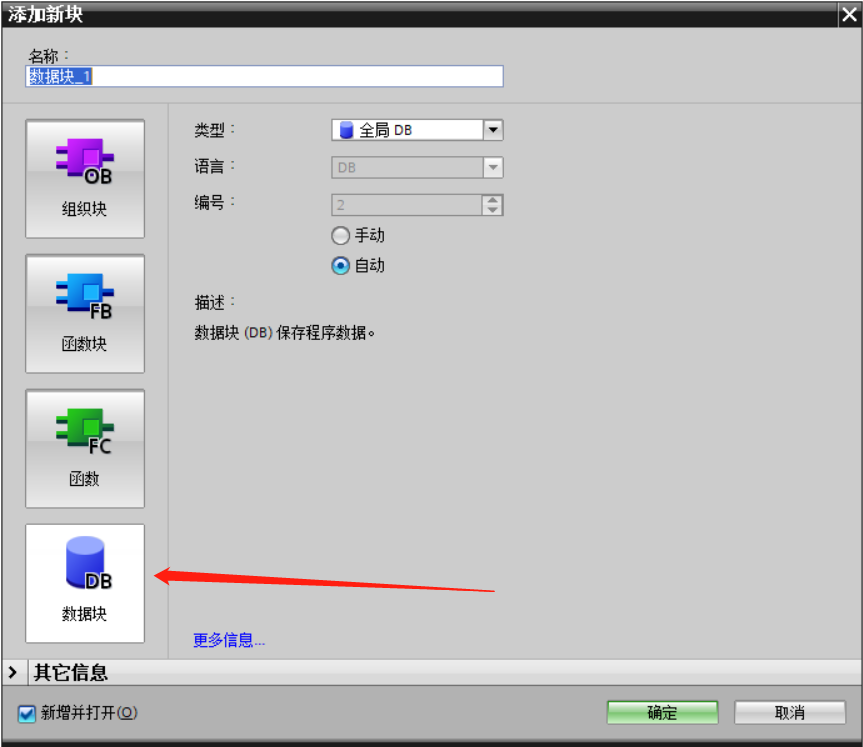 Figure 1-4
Second step, double-click to open the newly generated DB block, define the variable name as “aa”, and set the data type to “TCON_IP_v4” (you can copy TCON_IP_v4 into this dialog box), then press the “Enter” key. (Figure 1-5)
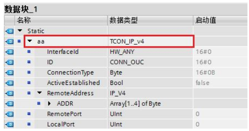 Figure 1-5
Create the data type for the TCP connection structure in MB_CLIENT
The definitions of each pin are as follows:
|
InterfaceId |
Hardware identifier. |
|
ID |
Connection ID, range from 1 to 4095 |
|
Connection Type |
Connection type. The default for TCP connection is: 16#0B |
|
ActiveEstablished |
Establish connection. Active is 1 (client), passive is 0 (server). |
|
ADDR |
IP address of the server side |
|
RemotePort |
Remote port number |
|
LocalPort |
Local port number |
The table shows the pin definitions of the TCON_IP_v4 data structure in Figure 1-5;
The remote server’s IP address in this article is 192.168.0.3, and the remote port number is set to 502. Therefore, the values for this data structure on the client side are:
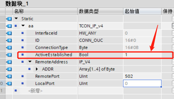 Figure 1-6
Note: The filling of the CONNECT pin needs to use symbolic addressing.

First step, create a global data block DB3, the creation method can refer to the above Figure 3, the name of the data block is shown in Figure 1-7:
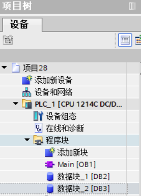 Figure 1-7
Second step, define a data type for an array to store data during communication, please refer to Figure 1-8:
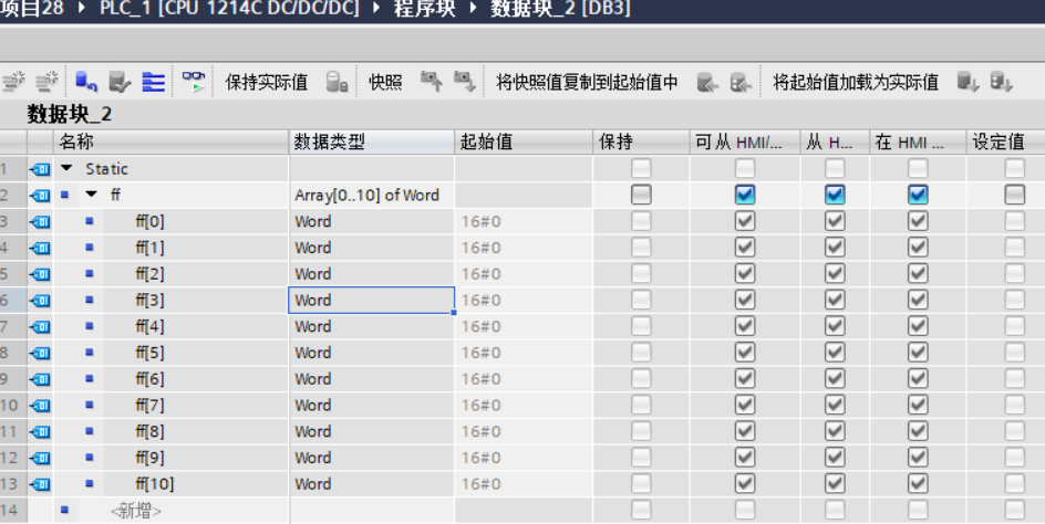 Figure 1-8
Note: The data buffer specified by MB_DATA_PTR can be in a DB block or M storage area address.
The DB block can be an optimized data block or a standard data block structure.
If it is an optimized data block structure, you need to fill this pin using symbolic addressing during programming; if it is a standard data block structure.
(You can right-click on the DB block, and in the “Properties” uncheck “Optimized Block Access” as shown in Figure 1-9), you need to fill this pin using absolute addressing. This article uses a standard data block (default) as an example for programming.
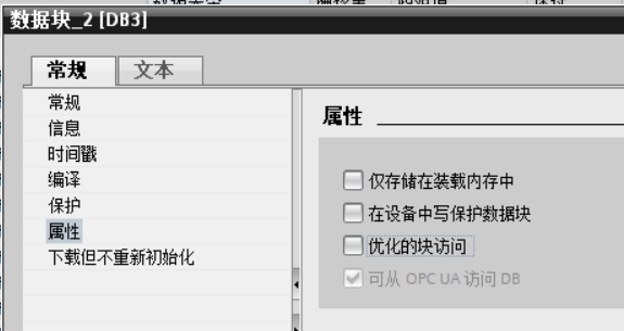 Figure 1-9

Call the MB_CLIENT instruction block to read the values of 2 holding registers from the Modbus TCP communication server, as shown in Figure 1-10:
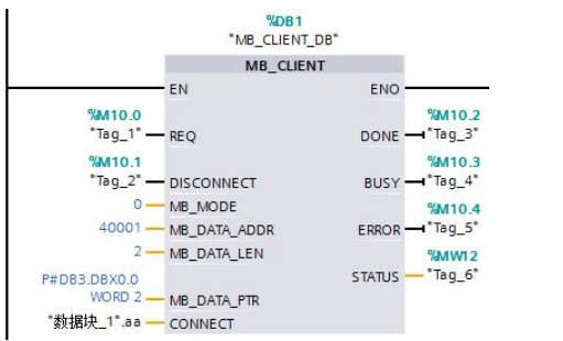 Figure 1-10
Download the entire project to S7-1200, when the Modbus TCP server side is ready, give a rising edge to the REQ pin of the MB_CLIENT instruction block, and the data read will be placed in the DB block specified by the MB_DATA_PTR pin. The specific experimental results can be viewed in the programming on the S7-1200 server side.
Today, Xiao Zhi shared the “Beginner’s Guide to TIA Portal Tutorial 30 (MODBUS TCP Client with S7-1200)”. You can bookmark it for use. If you encounter any problems or have any misunderstandings, you can message or comment. If you like it, please follow Xiao Zhi, like, and share, thank you!
Next article preview… (MODBUS TCP Server with S7-1200)