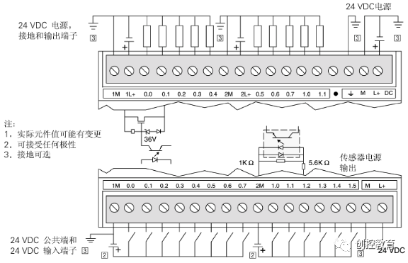
Hello everyone, today we will learn about the wiring of the Siemens S7-200 PLC and the S7-200 data storage areas:
First, let’s look at how to wire:
S7-200 Data Storage Areas:
1. Input/Output Image Registers: The addressing range of S7-200 PLC is (I0.0~I15.7). The input image register (this area can be operated bit by bit, also known as input relays) is driven by external signals, with normally open and normally closed contacts available for user programming.
The output image register: The addressing range of S7-200 PLC is (Q0.0~Q15.7). The output image register (also known as output relays) is used to transmit the PLC’s output signals to the load, with coils driven by program instructions. Each I/O point of the PLC is a specific physical point. The CPU 224 main unit has 14 digital input points from I0.0 to I0.7 and I1.0 to I1.5, and 10 digital output points from Q0.0 to Q0.7 and Q1.0 to Q1.1.
2. Variable Memory V
This is used to store intermediate results of calculations and other data. The CPU 224 has 5K storage bytes from VB0.0 to VB5119.7. It can be used bit by bit, byte, word, or double word.
3. Internal Flag Bit (M) Storage Area
M serves as a control relay (also known as intermediate relay), used to store intermediate operands or other control information.
The addressing range of S7-200 PLC is M0.0~M31.7, and data in the storage area can be accessed bit by bit, byte, word, or double word.
4. Sequence Control Relay (S) Storage Area
S, also known as status elements, is used to achieve sequence control and step control.
The addressing range of S7-200 PLC is S0.0~S31.7, and data can be accessed bit by bit, byte, word, or double word.
5. Special Flag Bit (SM) Memory
① SMB0 is a status byte that is updated by the S7-200 CPU at the end of each scan cycle, defined as follows:
SM0.0 RUN status monitoring, when the PLC is in RUN status, this bit is always 1.
SM0.1 is 1 on the first scan, when the PLC transitions from STOP to RUN status, ON (1 state) for one scan cycle, used for program initialization.
SM0.2 is ON for one scan cycle when data in RAM is lost, used for error handling.
SM0.3 is ON for one scan cycle when the PLC powers on in RUN mode.
SM0.4 is a pulse output, this bit outputs a time clock pulse with a 50% duty cycle, used as a time reference or simple delay.
SM0.5 is a second pulse, this bit outputs a second clock pulse with a 50% duty cycle, which can be used as a time reference.
SM0.6 is a scan clock, one scan cycle is ON (high level), the other is OFF (low level), alternating in a cycle.
SM0.7 indicates the switch position of the operating mode, 0 for TERM position, 1 for RUN position. When it is 1, it makes the free end communication mode effective.
② SMB1 is an instruction status byte, commonly used for tables and mathematical operations, with some bits defined as follows:
SM1.0 Zero flag, this bit is 1 when the calculation result is 0.
SM1.1 Overflow flag, this bit is 1 when the calculation result overflows or an illegal value is found.
SM1.2 Negative flag, this bit is 1 when the mathematical operation result is negative.
6. Local Memory (L)
The S7-200 has 64 bytes of local memory, with an addressing range of LB0.0~LB63.7, where 60 bytes can be used as temporary memory or to pass parameters to subprograms, and the last 4 bytes are reserved system bytes.
7. Timer (equivalent to time relay)
The timers in the S7-200 CPU are devices that accumulate time increments from the internal clock for time control. The addressing range is T0~T255 (22X); T0~T127 (21X).
8. Counter
Counters are mainly used to accumulate the number of input pulses. There is one 16-bit preset value and one current value register, along with one status bit. The current value register is used to accumulate the number of pulses, and the status bit is set to 1 when the current value of the counter is greater than or equal to the preset value. The S7-200 CPU provides three types of counters: increasing count, decreasing count, and up/down count. The addressing range is C0~C255 (22X), C0~C127 (21X).
9. Analog Input/Output Image Registers (AI/AQ)
The analog input circuit of the S7-200 converts external analog inputs (such as temperature, voltage, etc.) into a word length (16-bit) digital quantity, stored in the analog input image register area.
The addressing range for AI is AIW0, AIW2, … AIW62, starting addresses are defined as even byte addresses, with a total of 32 analog input points.
The S7-200 analog output circuit is used to convert a word length (16-bit) digital value from the analog output image register area into an analog current or voltage output.
The addressing range for AQ is AQW0, AQW2, … AQW62, starting addresses also use even byte addresses, with a total of 32 analog output points.
10. Accumulator (AC)
The accumulator is used to temporarily store data, and the S7-200 PLC provides 4 32-bit accumulators AC0~AC3. The accumulator supports access in bytes (B), words (W), and double words (D).
11. High-Speed Counter (HC)
The CPU 22X provides 6 high-speed counters HC0, HC1, … HC5 (each counter has a maximum frequency of 30KHz) to accumulate events faster than the CPU scan rate. The current value of the high-speed counter is a double-word signed integer.
(Content sourced from the internet, copyright belongs to the original author)Disclaimer: If there are copyright issues, please contact for deletion!Neither individuals nor organizations bear related legal responsibilities.