Siemens All-Subject + TIA Portal + EPLAN Electrical Drawing Video Recordings for Sale at Low Prices!
Chuangkong Education Siemens All-Subject Course Introduction
When it comes to Siemens communication, we must mention PROFIBUS. Do you know what it is? How to use it?
PROFIBUS supports master-slave mode and multi-master multi-slave mode. In the multi-master mode, the control of the bus is determined by token passing between the masters, and the master that obtains control can send and receive information from the slaves, achieving point-to-point communication.
1. Composition of PROFIBUS
The PROFIBUS protocol consists of three main parts: PROFIBUS-DP (Distributed Peripheral), PROFIBUS-PA (Process Automation), and PROFIBUS-FMS (Fieldbus Message Specification).
1.1 PROFIBUS-DP (Distributed Peripheral)
PROFIBUS-DP is a high-speed, low-cost data transmission protocol used for communication between control devices at the unit level and distributed I/O (such as ET 200) in automation systems. Communication between masters is token-based, while communication between master and slave is done through master-slave polling, as well as a combination of both methods. A network can have several passive nodes (slaves), while its logical token only contains one active token (master), making this a pure master-slave system. Figure 1 shows a typical master-slave PROFIBUS-DP bus, where one station is the master and the others are slaves.
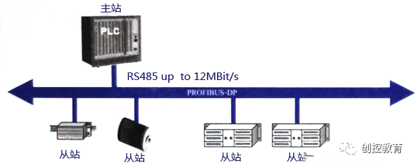
Figure 1 Typical Master-Slave PROFIBUS-DP Bus
1.2 PROFIBUS-PA (Process Automation)
PROFIBUS-PA is used for low-speed data transmission from field sensors and actuators in process automation, using an extended PROFIBUS-DP protocol. The transmission technology adopts the IEC 1158-2 standard and can be used for communication between sensors and actuators in explosion-proof areas and the central control system. Shielded twisted pair cables are used, powered by the bus. A typical configuration of a PROFIBUS-PA system is shown in Figure 2.
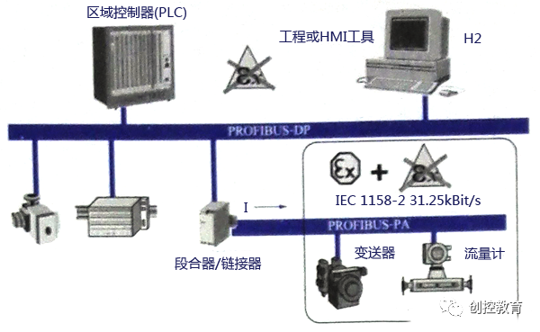
Figure 2 Typical PROFIBUS-PA System Configuration
1.3 PROFIBUS-FMS (Fieldbus Message Specification)
PROFIBUS-FMS can be used for workshop-level monitoring networks, providing a wide range of communication services for cyclic and acyclic communication services at medium transmission speeds. For FMS, the focus is mainly on system functionality rather than system response time. As shown in Figure 3, a typical PROFIBUS-FMS system consists of various intelligent automation units, such as PCs, PLCs, HMIs, etc.
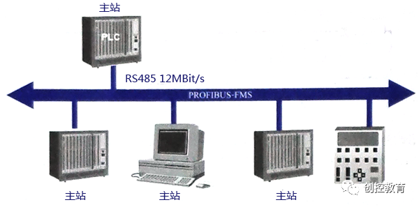
Figure 3 Typical PROFIBUS-FMS System
2. Structure of the PROFIBUS Protocol
The structure of the PROFIBUS protocol is based on the ISO/OSI reference model, as shown in Figure 4. The first layer is the physical layer, defining the physical transmission characteristics; the second layer is the data link layer; layers three to six are not used by PROFIBUS; the seventh layer is the application layer, defining the application functions.
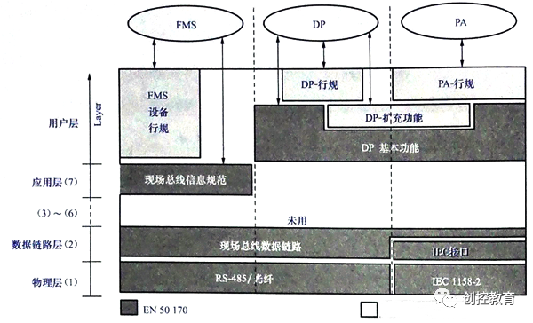
Figure 4 Typical PROFIBUS-FMS System
PROFIBUS-DP is an efficient and fast communication protocol that uses the first and second layers and the user interface, while the third to seventh layers are not used. This simplified structure ensures fast and efficient data transmission for DP.
3. Transmission Technology
PROFIBUS bus uses a bus topology structure with terminators at both ends, as shown in Figure 5.
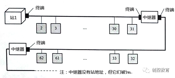
Figure 5 Bus Topology Structure with Terminators at Both Ends
PROFIBUS uses three transmission technologies: PROFIBUS DP and PROFIBUS FMS use the same transmission technology, which can utilize RS485 shielded twisted pair cables or fiber optic transmission; PROFIBUS PA uses IEC 1158-2 transmission technology; DP and FMS use the same transmission technology and unified bus access protocol, which can run simultaneously on the same cable; DP/FMS complies with EIA RS-485 standards (also known as H2), using shielded or unshielded twisted pair cables, at speeds ranging from 9.6kbit/s to 12Mbit/s. A bus segment can have up to 32 stations, and with repeaters, up to 127 stations. The transmission distance of DP/FMS is related to the transmission rate: at 3-12Mbit/s, it is 100m; at 9.6-93.75kbit/s, it is 1200m. Additionally, to accommodate environments with high electromagnetic interference or for long-distance high-speed transmission, PROFIBUS can use fiber optic transmission technology.
4. PROFIBUS Bus Connectors
PROFIBUS bus connectors are used to connect PROFIBUS stations with cables for signal transmission, equipped with built-in terminators, as shown in Figure 6.
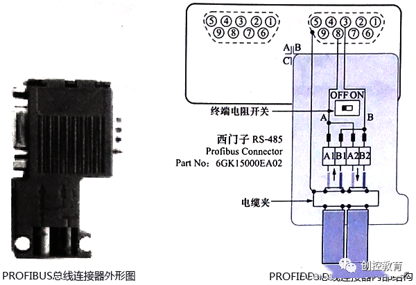
Figure 6 PROFIBUS Bus Connector
5. Correct Wiring Method for PROFIBUS-DP
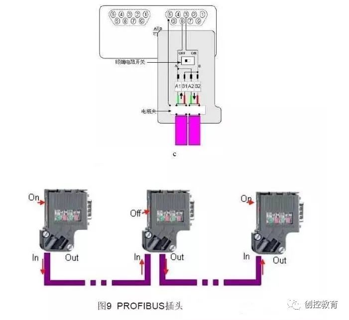
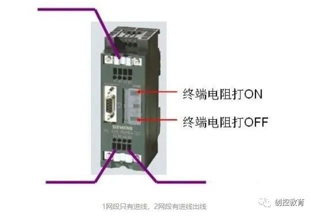
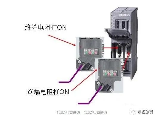
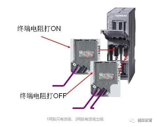
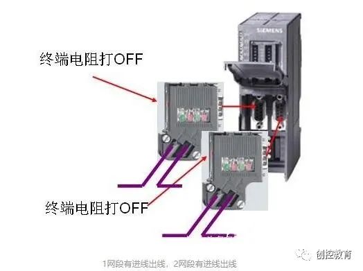
The correct wiring method is shown in the diagram below, which is self-explanatory. The PROFIBUS cable is simple, consisting of only two wires: one red and one green, with a shield layer outside. When wiring, ensure the shield layer is properly connected and does not contact the inner wires. Be clear about which wires are incoming and outgoing; if it’s a daisy chain, it means one main bus goes down with branches connected in between, which is a common method. At both ends of the bus, the wires must be connected to the incoming holes, not the outgoing holes. The switches at both ends must be set to the ON position, making only the incoming wire connected while the outgoing wire is disconnected. All other intermediate connections should be set to OFF, allowing both incoming and outgoing wires to be connected (memory aid: ON indicates connecting the terminator resistance, so the end connectors should be set to ON; OFF indicates disconnecting the terminator resistance, so the intermediate connectors should be set to OFF).
6. Step-by-Step Guide on How to Connect and Purchase
Whether forming an MPI or PROFIBUS-DP network, the main components used are the same:
For specific cable and connector order numbers, please refer to: Common Accessory Order Numbers
A. Cables and Strippers. Use FC technology without exposing bare copper wires.

Figure 1. PROFIBUS Cable with One End Stripped and Quick Stripper (FCS, Order Number 6GK1905-6AA00).
B. Open the PROFIBUS Network Connector. First, release the cable tension by opening the pressure block, then lift the core wire lock.
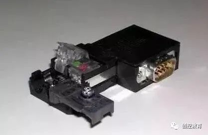
Figure 2. Opened PROFIBUS Connector
C. Remove the protective layer from the PROFIBUS cable core wire, insert the core wire according to the corresponding color markings into the core wire lock, and then press the lock block firmly to ensure contact of the internal conductors. Make sure the shield layer stripped from the cable contacts the shield connection pressure plate.
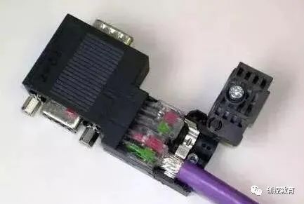
Figure 3. Inserting the Cable
Due to the higher communication frequency, the communication cable must be grounded at both ends. The shield layers at both ends must be connected.
D. Reset the cable pressure block, tighten the screws, and eliminate external tension on the internal connection.
Network connectors are mainly divided into two types: with and without programming ports. Connectors without programming ports are used for general networking, while those with programming ports can provide a programming connection while networking for programming or connecting to HMIs.
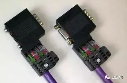
Figure 4. Left: Network Connector without Programming Port (Order Number: 6ES7 972-0BA52-0XA0), Right: with Programming Port.
Connecting the PROFIBUS cable to the network plug forms a bus-type network structure.
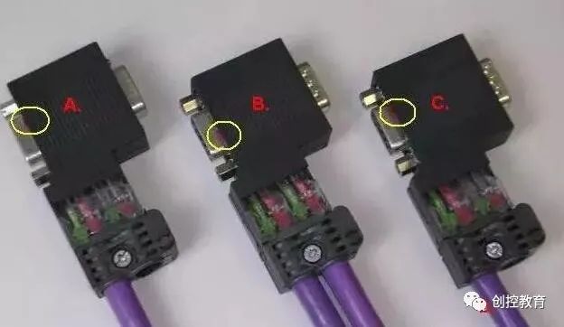
Figure 5. Bus-Type Network Connection
In the above figure, network connectors A, B, and C are plugged into the communication ports of three communication stations; cable a connects plugs A and B, while cable b connects plugs B and C. The linear structure can be expanded accordingly.
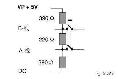
Note the setting of the “terminator resistance” switch within the circle. The terminator switch for the network terminal plug must be set to the “ON” position; the switch for the intermediate station plug should be set to the “OFF” position.
Precautions:
The device with the terminator resistance ON cannot be powered off. As shown in Figure 5, besides the 220-ohm terminator resistance, there are also two 390-ohm bias resistors, and the bias resistors must be connected to the power supply.
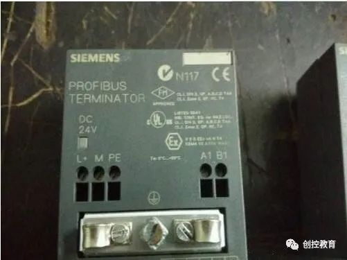
If the terminal device needs to be powered off frequently for maintenance, or if the terminal device only has terminal blocks and no 9-pin D-type socket, an active terminator module should be used as the terminator for the PROFIBUS bus (6ES7 972-0DA00-0AA0).
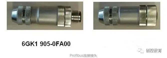
If the PROFIBUS cable is not long enough and two cables need to be connected, simply twisting the two copper cores together is not advisable, as this will damage the cable’s characteristic impedance and may lead to communication issues. It is best to use the connector shown in Figure 7 to connect the two cables that need to be joined.
3 How to Use the Terminator Resistance on RS485 Repeaters
The maximum length of PROFIBUS communication cables depends on the baud rate of communication. If the cable exceeds the maximum communicable length, RS485 repeaters should be used to extend the communication distance.
There are terminal blocks on the repeater, and the PROFIBUS cable can be directly connected to the terminals. The usage is the same as for the cable plug.

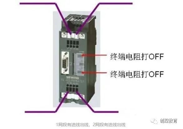
4 How to Use the Terminator Resistance on OLM Plugs
If the communication distance for field devices is far, or if there is serious electromagnetic interference on-site, OLM can be used to convert electrical signals into optical signals, using optical cables for signal transmission. The OLM has an RS485 electrical interface and requires a PROFIBUS plug to connect the cable. The wiring method for the OLM electrical interface is the same whether connecting to a master or a slave.
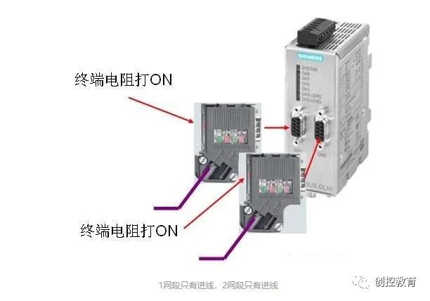
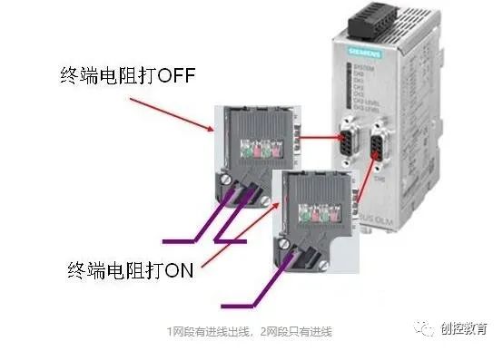
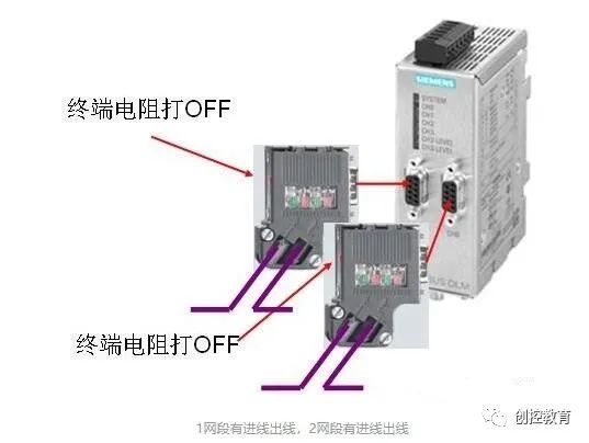
For OLMs with only one RS485 interface, it can be regarded as having only one network segment, and the wiring method is the same.
5 How to Use the Terminator Resistance on DP/DP Couplers
Two DP masters can use a DP/DP coupler to transmit data. The DP/DP coupler has two RS485 interfaces, and the connection method is the same as for OLM.
In fact, many times, PROFIBUS-DP gives people a sense of insecurity, mainly because its operational coefficient is a bit high, but as long as all work is done very well, it is also very stable.
Although more and more people prefer to use PROFINET, there are still many old devices using PROFIBUS-DP, so mastering it is also very necessary!
(Content sourced from the internet, copyright belongs to the original author)
Disclaimer: If there are copyright issues, please contact to delete!No person or organization bears any legal responsibility.
Siemens All-Subject + TIA Portal + EPLAN Electrical Drawing Video Recordings for Sale at Low Prices!
Chuangkong Education Siemens All-Subject Course Introduction
Schneider PLC Training Videos Available for Free Limited Time (Not only can you learn for free but also receive gifts, and upon passing the exam, a certificate of completion will be awarded)