Click↑↑Technical Training, follow and pin to subscribe for free for a long time
180,000+ industrial control professionals are following the WeChat platform: technical sharing, learning exchange, industrial control videos
This article introduces how to achieve communication between Modbus and Profibus-DP protocol devices, the application of the Modbus to Profibus-DP gateway PM-160, and the communication methods in these two different protocols in the communication between Siemens S7-300 PLC and Yokogawa CS30 DCS control system.
Currently, PLCs, DCS, and smart instruments are widely used in field production control systems and have developed into distributed industrial control systems that collaborate and address the entire production process. This article introduces the application of the Modbus to Profibus-DP protocol gateway device in a distributed control system project for a certain water conservancy station.
1. System Composition
1.1 System Structure
The system is structured as shown in the figure below, excluding other field-level control devices besides the Siemens S7-300 PLC. The upper-level computer adopts the Yokogawa CS3000 DCS control system to achieve centralized monitoring of the entire water conservancy project. One of the lower-level machines is the Siemens S7-300 PLC, used to control the start and stop of various smart instruments on site, including field motors, smart switches, inverters, sensors, and other execution and detection devices, as well as information collection.
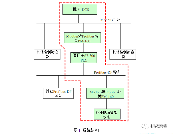
In the system structure shown in the above figure, various smart instruments on site (use Modbus protocol or various non-standard protocols, with interfaces of RS485, RS422 or RS232) can be connected to the Siemens S7-300 PLC through the general serial port (Modbus/RS-485/RS422/RS232) to the Profibus-DP gateway PM160. At this time, the protocol type of the gateway PM160 on the serial port side is Modbus master or general mode.
The Yokogawa DCS also needs to use the general serial port (Modbus/Rs485/R5422/RS232) to Profibus-DP gateway PM-160 for data collection and monitoring of the Siemens S7-300PLC, where the gateway PM-160 on the serial port side is a slave.
1.2 Communication Network Composition
PROFIBUS fieldbus communication protocol includes three main parts.
PROFIBUS DP: Communication between master and slave uses a polling method, mainly applied to unit-level and field-level communication in automation systems.
PROFIBUS PA: Power and communication data are transmitted in parallel through the bus, mainly used for unit-level and field-level communication in process automation systems.
PROFIBUS EMS: Defines the communication model between masters, mainly used for system-level and workshop-level process data exchange in automation systems.
1.3 Modbus Protocol
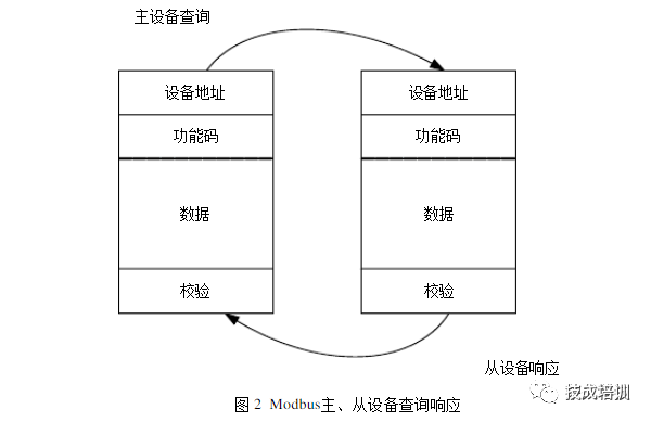
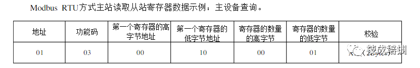
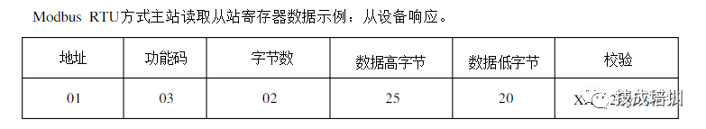
The Modbus protocol is a master-slave serial communication protocol suitable for the industrial control field. It uses a query communication method for information transmission between master and slave devices, with an addressable range of 1-247 devices. The protocol includes two types of queries: broadcast query and individual device query, with the difference being that the broadcast query does not require a response from the slave device. The communication process between the master and slave devices is shown in the figure below.
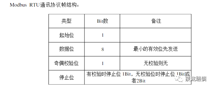
The Modbus protocol has two transmission modes: ASC mode and RTU mode. At the same baud rate, the RTU mode can transmit more data than the ASC II mode, so industrial networks mostly use the RTU mode. The information transmission message format in RTU mode is shown in the figure below:
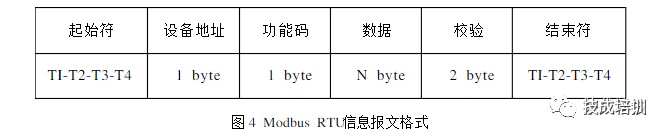
It does not have start and stop bits but uses a minimum of 3.5 character interval time as the start and end markers of the information. All character bits in the information frame consist of hexadecimal characters 0-9,AF.
1.4 Network Composition and Hardware Introduction
As shown in Figure 1, in this system design, there are two networks that use the Modbus to Profibus- DP gateway PM-160. The role of the gateway in these two networks is different, where:
In the upper network (establishing communication between Siemens S7-30PLC and Yokogawa DCS), the Modbus to Profibus-DP gateway PM-160 acts as a Modbus slave on the Modbus side and as a slave on the Profibus-DP side, establishing communication between the Profibus-DP master (Siemens S7-300PLC) and the Modbus master.
The DCS communication part uses a Yokogawa communication module model ALR121, along with the Modbus communication software package provided by Yokogawa. This communication module has a maximum communication data capacity of 40 words. Through the gateway configuration software, the PM-160 is configured to convert, store, and map the read and write commands and data of the DCS to the input and output image areas of the Siemens PLC to achieve real-time transmission of control information between the upper and lower computers.
In the lower network (establishing communication between Siemens S7-300PLC and field smart instruments), the Modbus to Profibus- DP gateway PM-160 acts as a Modbus master on the Modbus side and as a slave on the Profibus-DP side, establishing communication between the Modbus slaves (various field smart instruments, motors, smart switches, inverters, sensors, etc.) and the Profibus-DP master Siemens S7-300PLC.
2. Modbus to Profibus-DP Gateway PM-160 Configuration
2.1 Hardware Configuration
The Profibus-DP slave address of the PM-160 can be set using the hardware rotary switch or configuration button of the gateway. The rotary switch has two positions, the left position sets the high address (tens) and the right position sets the low address (units). The gateway PM-160 can be set to normal operating status or configuration status using the dip switch. When the PM-160 is in configuration mode, the user can set relevant read and write commands and parameters through the accompanying configuration software.
PM-160 provides three serial ports: RS485, 422, 232, enabling Modbus slave, master devices, and non-standard serial devices to connect and communicate with the gateway PM-160 through these three interfaces. The PM-160 does not have built-in terminal resistors; when performing RS485 communication, please ensure to add a terminal resistor (120 ohms) at each end of the RS485 bus.
2.2 Software Configuration
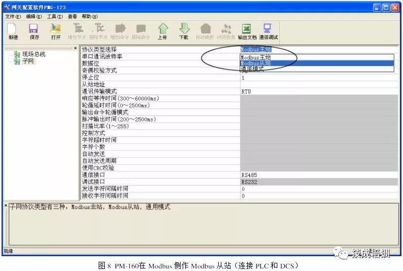
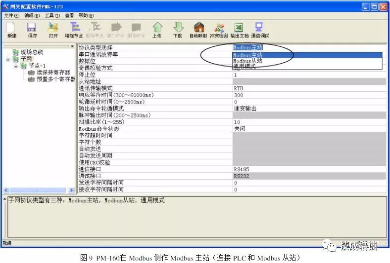
1) Use the accompanying software to set the relevant parameters and commands of the field network and subnet for PM-160. Set the PM-160 to configuration mode using the dip switch, open the installed configuration software, and when achieving communication between PLC and DCS, set the subnet protocol type to Modbus slave, and configure the serial communication baud rate, data bits, parity bits, stop bits, and the address of PM-160 as a Modbus slave, along with the communication interface.
Among them, the settings for serial communication baud rate, data bits, parity bits, and stop bits should match those of the connected Modbus master device (DCS).
When achieving communication between PLC and Modbus devices, set the subnet protocol type to Modbus master and configure the serial communication parameters, communication transmission mode, and communication interface. The settings for serial communication parameters should match those of the connected Modbus slave device.
In the above figure, the “node-1” indicates that the connected slave device address is 1, with two commands configured: “read holding register” and “preset multiple registers”, indicating that the gateway has read data from the corresponding address of the slave, and can output data to the Modbus slave device. The command configuration method is as follows:
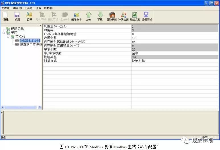
The starting address of the Modbus register: the user inputs the starting address of the target data to be collected;
Number of data: the number of registers or coils of the target data;
Memory mapping starting address: the corresponding memory buffer address of the Modbus slave device data.
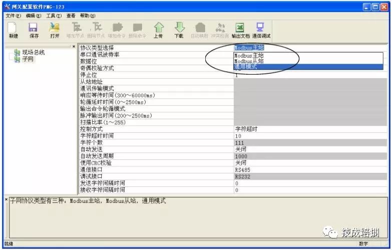
When achieving communication between PLC and non-standard protocol devices, set the subnet protocol type to general mode and configure the serial communication parameters, control mode, and communication interface. The serial communication parameters should match those of the connected non-serial devices (field smart instruments), and the PM160 supported general mode is transparent transmission mode.
2), Configure the gateway PM-160 in STEP7
In the hardware configuration interface of STEP7, import the GSD file corresponding to PM-160 and add the configuration file of PM-160 to the device configuration library of STEP7. Users can find the registered device in the hardware configuration interface:
Catalog->PROFIBUS DP->Additional Field Devices->General->CONVERTER->PM-160.
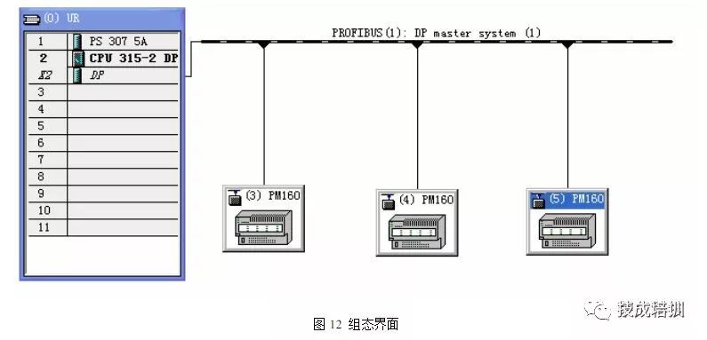
After adding PM-160 to the configuration page of STEP7, relevant data blocks can be inserted for address mapping in the image area. The data blocks provided by PM-160 are as follows:
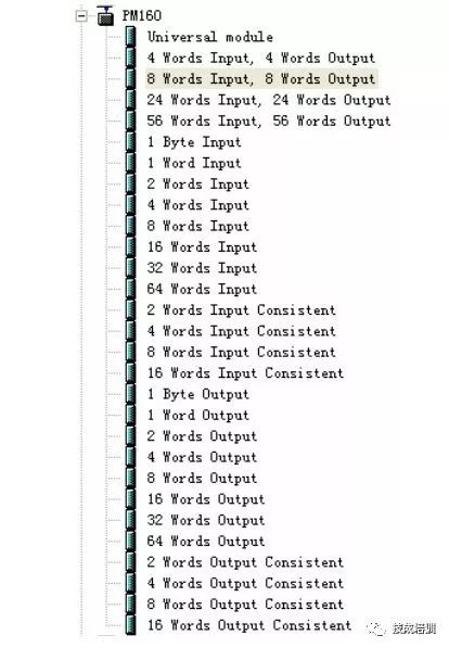
Push the required input and output data blocks to the corresponding slot of the gateway. As shown in the figure below:
3. Data Read and Write
3.1 DCS Read and Write PLC Data
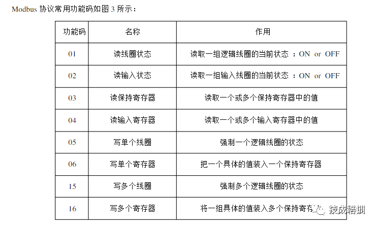
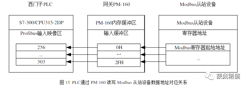
The DCS, as a Modbus master, reads and writes PLC data through PM-160, using the 04 function code to read data, with the corresponding register starting address of OH (30001H), and using 10H (03H) function code to write data, with the corresponding register starting address of OH (40001H).
3.2 PLC Read and Write Field Smart Instrument Data
3.2.1 PLC Read and Write Modbus Slave Device Data
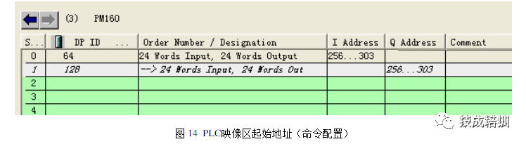
The PLC sends Modbus master instructions to read and write data from field serial devices through PM-160. The mapping starting address in the image area corresponds to the memory mapping starting address of the gateway as shown in the following configuration.
3.2.2 PLC Read and Write Non-standard Serial Device Data
The first two bytes of the PLC’s output mapping area represent the length of the sent serial data and the transaction sequence number, while the rest are the serial data to be sent. The transaction sequence number changes, and the PLC sends a corresponding length of serial data.
In this system, the Modbus to Profibus- DP gateway PM160 plays three roles:
Establishing connection communication between the Modbus master and the Profibus- DP master (Modbus master mode);
Establishing connection communication between the Modbus slave and the Profibus- DP master (Modbus slave mode);
Establishing connection communication between non-standard serial devices and the Profibus-DP master (general mode).
Since the operation of this communication system, the entire system communication has been normal, effectively ensuring the normal operation of the entire water conservancy engineering control system. Using the Modbus to Profibus-DP gateway greatly facilitates the control and operation of industrial automation sites.
Source: Internet, infringement deletion
If you find this article helpful, please give it a thumbs up! 
Click↓Read the original to learn electrical knowledge such as electricians and PLC for free!