Testing and Measurement Tools
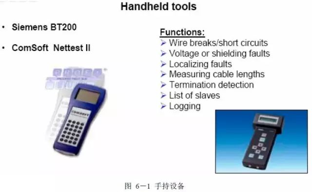
1. Handheld Devices
Handheld devices are specially developed for testing PROFIBUS cables with RS 485 interfaces. For example, Siemens BT200 (recommended) and ComSoft Nettest II. Handheld devices can test the installation, as well as check the PROFIBUS cables and stations. To use the handheld device, it must be connected to the PROFIBUS cable via a 9-pin D-type connector. Typically, oscilloscopes and multimeters can also be used to test the PROFIBUS bus. Oscilloscope testing can effectively identify faults in the PROFIBUS bus, while multimeters can perform some principle measurements.
BT200 is a tool for detecting the RS485 physical layer, easy to operate without the need for other diagnostic tools. During the installation phase, using the BT200 testing device can test the PROFIBUS cable, and after the site is connected, it can also test the wiring, quickly and simply detecting installation errors. Before system debugging, the RS 485 interface of the PROFIBUS DP station can be tested. Even if there is no master station on the PROFIBUS DP, it can list all slave stations connected to the installation bus, allowing for pre-testing of the operational capacity of individual bus segments, reducing debugging time.
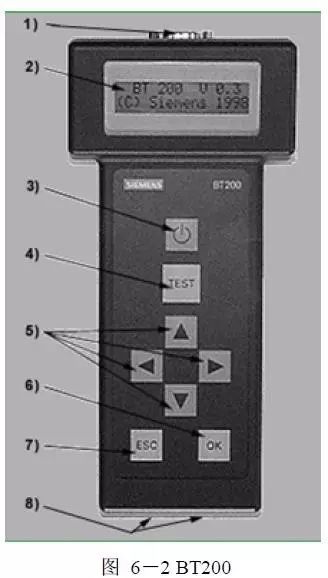
The operation interface of the BT200 is as follows:
① PROFIBUS-DP interface (9-pin D-type socket)
② LCD display (2X16 characters)
③ “On/Off” button
④ “Test TEST” key (start detection)
⑤ “Cursor” key
⑥ “Confirm OK” key
⑦ “Exit ESC” key
⑧ Charging contacts.
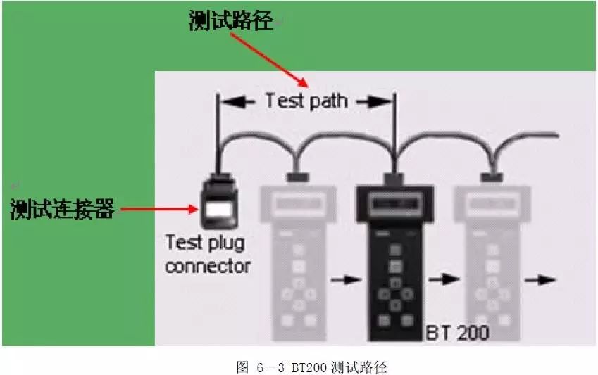
Testing the network with the BT200 can be divided into normal mode and expert mode. In normal mode, only the wiring status can be tested. The bus connection test is conducted between the BT200 and the test connector (Test plug connector). During the system device installation phase (when the device is powered off), the test connector is installed at one end of the bus segment, and the BT200 tests the bus segment sequentially. Both ends of the bus segment need to be equipped with terminating resistors.
The above figure shows the principle of sequential measurement, measuring the bus segment one by one, sequentially excluding whether each segment of bus cable A, B is short-circuited, and whether there is a fault with the shielding layer. If no stations are connected to the bus, only the bus cable is tested. If the test is completely successful, it will display Cableling o.k.(1R)→OK (cable normal, only one terminating resistor on the bus) or Cableling o.k.(2R)→OK (cable normal, two terminating resistors on the bus). Various fault information displayed on the BT200 can be referred to in the product manual.
Through the measurements in normal mode, errors such as site connection interruption, wiring reversal, short circuits, AB phase or shielding layer disconnection, and no or more than 2 terminating resistors can be detected. If further testing is needed, the BT200 can be switched to expert mode. By pressing the “ESC” and “OK” keys simultaneously, the device can be switched from normal mode to expert mode.
Expert mode not only has all the functions of normal mode but also includes RS485 interface testing, path testing, network distance measurement, and signal reflection testing.
1. Site (RS 485) Testing
Connect the BT200 to the powered slave station; for the RS485 interface of a single slave station, it can detect whether RS485 is normal or damaged, and also measure the actual bus level (5V); if the BT200 does not respond, it indicates that no signal has been received or the slave station address is set incorrectly. If signals are not continuously received, testing needs to be repeated.
2. Path Testing
Path testing can test the entire network across repeaters or fiber optics, not only detecting whether all slave stations on the PROFIBUS bus are activated but also displaying the found station addresses, such as 1, 4, 5, 9, 10, 11, 12→OK.
3. Distance Testing
The BT200 can measure the length of the PROFIBUS cable.
4. Reflection Testing
This can be used to determine whether faults exist (such as disconnections and short circuits) and to confirm whether the results of distance measurements are correct.
Reflections can occur in the following situations:
● There are branch lines;
● Too many terminating resistors or no terminating resistors;
● The measurement path contains other types of cables;
● Cables are incorrectly installed (such as poor terminal contacts, etc.).
All of the above faults can be detected through reflection testing.
2. Oscilloscope Measurement
Using an oscilloscope for measurement can effectively identify PROFIBUS faults. By analyzing the waveforms of signals measured with different qualities, relevant fault information can be obtained.
1) Technical Prerequisites
The oscilloscope used for PROFIBUS measurement needs to have the following characteristics:
Design: Digital storage oscilloscope
Bandwidth: 100MHz
Channels: 2, electrically isolated from each other and separate from the device ground (network connection)
Trigger: Internal + External
Coupling type: DC
When measuring with an oscilloscope, ensure that the voltage between the two input channels is isolated and separated from the device ground. The isolation between the two channels ensures that they do not affect each other. Both channels should also be electrically isolated from the device ground. If this is not the case, an accidental connection of one channel to a live cable core may cause a short circuit.
For PROFIBUS measurements, typically the channel ground is connected to one of the data lines. If an oscilloscope without electrical isolation is used, measurement cannot be performed, as the signals on the data lines are referenced to ground. Generally, these measurements are not allowed during system operation, as the connection of the ground to the data line will cause communication failures. However, if the two signals are measured separately and then isolated from each other, this can be avoided. In this case, electrical isolation between the two channels is not required.
2) Measurement Auxiliary Equipment
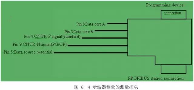
When measuring with an oscilloscope, a 9-pin D-type connector is usually used as a measurement auxiliary device. Figure 6-4 indicates which pin can measure which signal. The PROFIBUS connector connected to the programming device is the most suitable measurement auxiliary device. If the PROFIBUS structure does not have a programming device connection, using auxiliary devices for testing is very convenient. This measurement plug can be inserted between the PROFIBUS station and the PROFIBUS cable.
For some PROFIBUS stations, such as programming devices or operation panels, the CNTR signal is not sent on standard pin 4. For these PROFIBUS stations, pin 9 is used. For some operation panels, the CNTR signal must also be activated, for example, via DIP switches.
3) Measuring PROFIBUS RS 485
Measurements of PROFIBUS RS 485 must be performed at the interfaces of each PROFIBUS station. If only individual PROFIBUS stations are faulty, it is best to perform measurements at those (faulty) stations. The measurements can be classified into the following specific measurements:
● Data line B to data line A
Using an oscilloscope to measure the data signal from data line B to data line A (it is best to set the input voltage level to at least 1V/differential), the differential signal B-A between line B and line A will be obtained, which is the actual signal waveform of PROFIBUS. Using differential signal transmission for messages has the following advantages: since the noise distribution voltage affecting both data lines is uniform, the noise on the cable core A minus the noise on the cable core B is almost zero, thus eliminating the residual noise voltage in the actual data message.
Using an oscilloscope with isolated channels, the differential voltage B-A can be measured directly. When measuring, connect the ground terminal of one channel to data line A and the signal terminal to data line B, thus obtaining the actual signal waveform of PROFIBUS, as shown in the previous figure 3-4.
The voltage difference measured between high and low levels between B and A should be between 4V and 7V. The positive and negative voltage values should be approximately the same. In practice, this difference is about 0.5V. Many PROFIBUS stations provide repeater control signals CNTR-P (direction control signal). When the PROFIBUS station sends messages, this CNTR-P signal has a logic high level (about 3V to 5V). We can use this signal to check a specific PROFIBUS station. At the same time, the rising edge of the CNTR signal can be used as the trigger signal for the oscilloscope to observe the transmission of each PROFIBUS station. The CNTR signal can also be used to probe the messages associated with the master and slave stations. The master station’s message is the one that precedes the slave station’s message on the PROFIBUS.
● Measuring data line A or B against data ground
Measuring data line A or B against data ground can check the signals on each data core and detect faults such as defective bus drivers. However, these measurements must be performed directly at each PROFIBUS station, which can be quite cumbersome. Therefore, this measurement will only be performed if the measurement of data line B against data line A has already identified a fault. When performing measurements, the following two points must be noted: 1> Ensure that the data ground of each PROFIBUS station is not interconnected through the PROFIBUS cable. Because measurements must be made against the data ground for each data line, only the signals sent from the PROFIBUS station can be correctly displayed. The CNTR signal is simultaneously transmitted through the PROFIBUS station, which can verify this. 2> Measurements must be made using the interface’s data ground as the data ground. The following voltages can be measured at the interface:
★ Static voltage: Data line A: about 2V
★ Static voltage: Data line B: about 3V
★ Minimum transmission state voltage data line A: about 1V
★ Minimum transmission state voltage data line A: about 4V
★ Minimum transmission state voltage data line B: about 1V
★ Minimum transmission state voltage data line B: about 4V
For newer devices, due to stronger bus drivers, the maximum voltage on the data lines may be slightly higher. However, on both data lines, the minimum and maximum values should be similar. If this is not the case, one of the bus drivers may be defective.
3. Typical Signal Waveforms
● PROFIBUS cable too long
Too long cables usually act as capacitors, altering the shape of the signal. As a result, the rising edge of the square wave signal becomes rounded. The longer the PROFIBUS cable, the more pronounced this effect becomes. If the signal is altered too severely, it may cause the receiver to fail to correctly identify the signal. This is why the signal should reach the full voltage level at least by 50% of the bit period.
● Unconnected PROFIBUS plug
In PROFIBUS bus faults, another source of fault is the PROFIBUS plug, which appears to be plugged into the cable but is not actually connected to any PROFIBUS station. From the previous content, we know that in order to reduce signal emissions caused by shorted lines at high transmission rates (≥3MBit/s), inductors have been integrated into the PROFIBUS plug. If a PROFIBUS station is not connected to the PROFIBUS plug, the disconnected connector along with the inductor will generate signal interference. This interference should not exceed 0.5V.
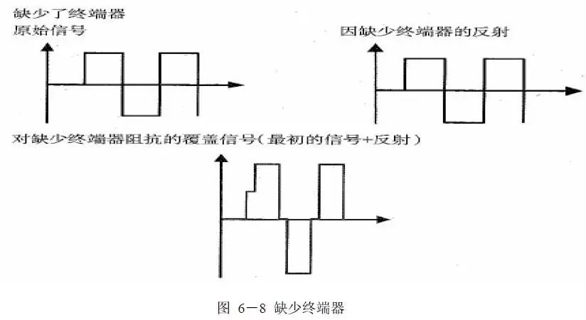
● Defective bus terminators
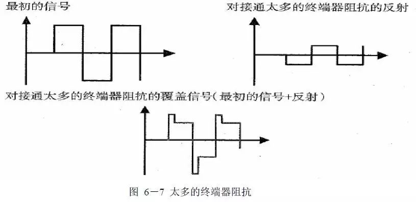
For bus connections, two types of incorrect bus terminator connections can cause PROFIBUS signal reflections. The reflection intensity is related to the specific connection:
1) Too many terminators are connected on the bus. Thus, about 1/3 of the signal is reflected, and relative to the original signal, the signal is rotated 180º. Then, it runs back to the PROFIBUS cable and may encounter the next transmitted message. If these two signals overlap at the crossover point, the level is reduced if the signal waveforms are parallel, and increased if the signal waveforms are in the same direction.
2) Too few terminators are connected on the bus. This situation can also cause reflections, but the reflection does not rotate 180º relative to the original signal; the signal returns at full height. If the reflected signal encounters the next data signal, the two signals may cancel each other out or create a signal that is double high. When the message is reflected and covered, these signals show a stair-step waveform. The waveform can vary due to the measurement position and the running cable. Due to different start times of various signals on the PROFIBUS, the cable message and reflection meet at different points.
4. Multimeter Measurement
In the absence of handheld devices and oscilloscopes, a multimeter can be used for some principle tests, such as testing the PROFIBUS cable, bus connectors, and loop impedance. These tests cannot provide 100% accurate values but can provide a rough indication. At the same time, these measurements must meet the following prerequisites:
(1) The same components (PROFIBUS cable and plugs) must be used throughout the segment, PROFIBUS components should not be connected, and the PROFIBUS cable must be disconnected. The cable can be determined to be disconnected by measuring the voltage between the shield and the two data lines.
(2) All terminators must be disconnected; if there are permanently connected PROFIBUS components in the system, such as repeaters, these components should be disconnected. Each segment must be measured separately.
Using a multimeter can discover and locate the following faults:
● Simple data line “reversal”
● One of the two data lines is interrupted
● Cable shielding terminal
● Short circuit between the two data lines
● Short circuit between the data line and cable shielding
1) Determining Loop Impedance
Loop impedance can be determined by measuring the impedance between the two cores of the PROFIBUS cable. The impedance of the cores depends on the cable structure and is also temperature-dependent. Specific cable impedance is usually specified in ohms (ohms) per km at a given temperature. It corresponds to the loop impedance of a 1km long PROFIBUS cable. The typical value for PROFIBUS RS 485 cable type A is 110 ohm/km at 20ºC. However, for special cables, such as highly flexible cables, this value may deviate. The cable impedance increases by 0.4% for every 1ºC rise in temperature. Measuring the cable loop impedance is relatively straightforward.
At one end of the PROFIBUS cable, data line A and data line B must be shorted (or bridged). Then at the other end of the cable, measure the loop impedance between the two cores. In the data sheet of the PROFIBUS cable manufacturer, check the specific loop resistance (ohm/km) of the cable used. For short cables (less than 50m), the loop impedance may be 0. Using this specific loop impedance, the length of the cable segment can be assessed:
Length (km) = Measured loop impedance (ohms) / Specific loop impedance (ohm/km):
Knowledge of the cable length can also be used to assess the cable loop impedance:
Loop impedance, Rloop (ohms) = Cable length (km) × Specific loop impedance (ohm/km)
Example
A segment of PROFIBUS RS 485 type A cable with a loop impedance of 20 Rloop Ω at 20ºC can be evaluated as follows:
20Ω/(110Ω/km)=0.182km=182m
2) Testing PROFIBUS Cable and Bus Connectors
Before starting the tests, all stations must be disconnected from the cable, and all terminators must be closed or disconnected. The following five steps should be completed on each PROFIBUS segment as described. Step 1 checks that the cable has no voltage from the power supply terminators; Step 2 checks for short circuits between the cable lines; for Steps 3 and 4, introduce a short circuit between the selected pins in the first connector and conduct these measurements on each of the remaining connectors. If a short circuit introduced on a certain connector fails, it indicates that the cable is bad or incorrectly connected. The steps must be completed in the correct order to thoroughly check that the cable has no wiring errors. Step 5 is used to check the cable length by introducing a short circuit between line A and line B at the first connector and measuring the loop impedance at the last connector.
● Step 1
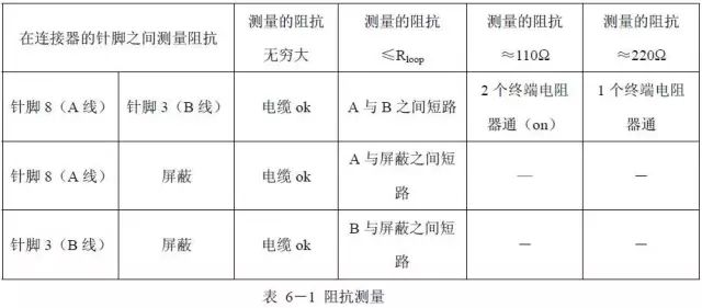
Using the low DC voltage range on the multimeter, check that the voltage between the shield and connector pins A and B is 0. If any voltage is found, it indicates that the cable is not disconnected from all devices or is still connected to powered terminators.
● Step 2
Measure the impedance between the connector pins on each connector. If the measured impedance is infinite (failure), it indicates a short circuit or a terminator resistor is connected. To perform the measurement, the cable loop impedance Rloop must be assessed. This can be achieved using the method described earlier. Locating a short circuit on the PROFIBUS cable can be difficult, as a fault in just one connector will cause the entire cable to appear shorted. One solution is to isolate each part of the cable until the short circuit disappears. However, it must be noted: the connected terminator resistor will introduce 220Ω of impedance between line A and line B. Only when no short circuit is found and all terminators are disconnected can Step 3 be performed.
● Step 3
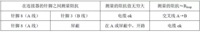
A short circuit must be introduced between pin 8 (line A) and the shield in the first connector of the segment being tested. In the first connector, a link can be made from pin 8 to the shield to complete the short circuit. Then, perform these measurements on each of the other connectors.
● Step 4
A short circuit must be introduced between pin 3 (line B) and the shield in the first connector of the segment being tested. In the first connector, a link can be made from pin 3 to the shield to complete the short circuit. Then, perform these measurements on each of the other connectors.
● Step 5
When measuring, a short circuit must be introduced between pin 3 (line B) and pin 8 (line A) to measure the cable loop impedance. A link can be introduced between pins 3 and 8 in the first connector to complete the short circuit. Then, measure the loop impedance between pins 3 (line B) and 8 (line A) at the last connector.