Recently, I used the S7-1200 to collect data from a certain flow sensor via Modbus-RTU. The Siemens side chose the CM1241 (RS422/485) (order number 6ES7 241-1CH32-0XB0, firmware version V2.2), and the CPU is 1214C with firmware version V4.2. I thought the debugging would be simple, but it took a lot of time, and I consulted many materials and videos before achieving communication. Below, I will gradually introduce the steps, possible pitfalls, and solutions.
1. Hardware Wiring
The 9-pin socket of the communication card uses pins 3 and 8 for 485 communication (Modbus communication). The Siemens manual indicates: 3+ (B), 8- (A), while the flow sensor indicates A+, B-. When communication was not established, I struggled here for a long time, and later resolved it by directly measuring the voltage with a multimeter. Principle: Ignore AB, just measure the voltage, + to +, – to – is sufficient. When communication is not established, the voltage is between 3-5VDC.
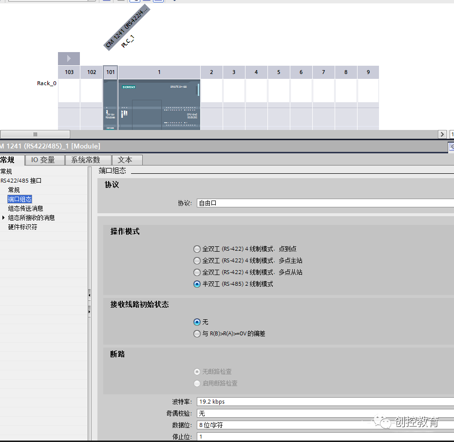
2. Hardware Configuration
Basic configuration (must be consistent with the slave), note the hardware identifier: here it is 269.
3. Port Initialization Programming
Be careful to choose the V3.1 program set, do not mix it with the V2.2 program below (note the version limitation of this program: “Use CM1241 from firmware version V2.1…”).
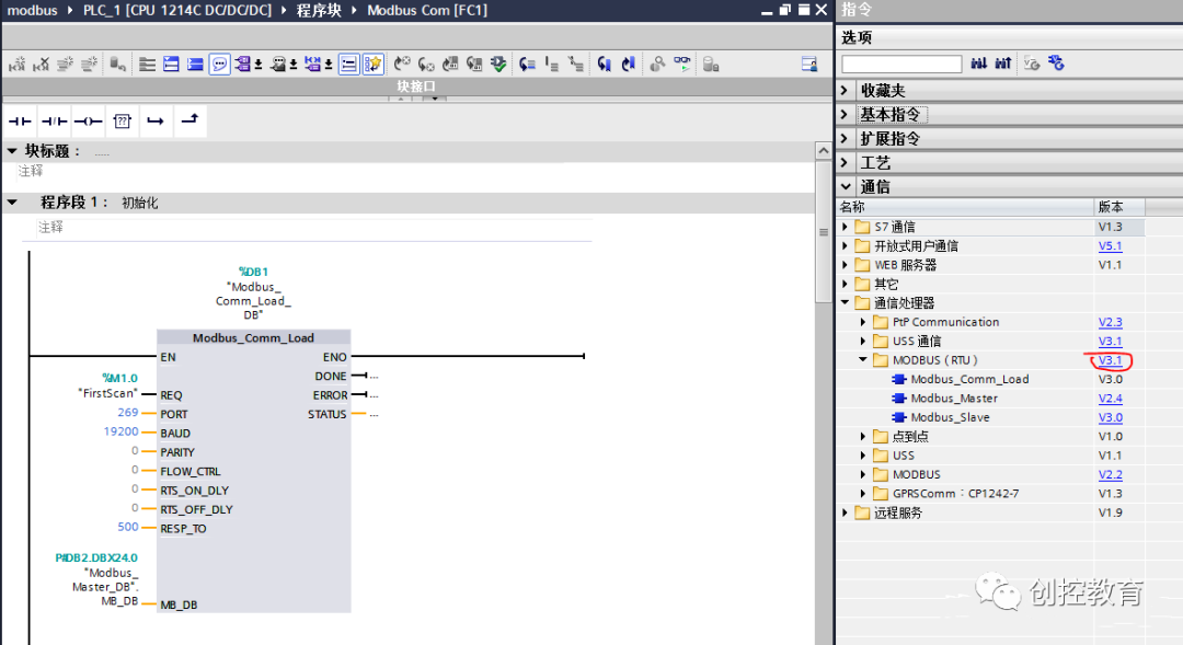
The initialization program is placed in the subroutine called by OB1 cyclically. The official reminder is not to place it in OB100 (the startup program). Set the parameters (generally consistent with the hardware), and the background data block at the top is automatically generated (here it is DB1).
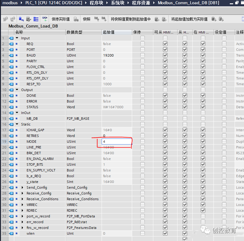
Open DB1 and change the MODE inside to 4, keeping other default values (this is also a major pitfall; who would think of modifying the background data block? All necessary modifications should be exposed through interface parameters!).
MB_DB must be consistent with the background data block of Modbus_Master later. When creating Modbus_Master, it will be automatically generated, and then you can go back and modify it. I have it as DB2.
4. Create Read/Write Instructions
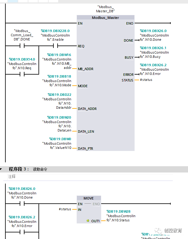
Here I used polling, so the program is relatively complex and will call multiple Modbus_Master modules (note: they must use the same background data block, do not create a new one each time). If it is just a single station read, the REQ end can just use a clock pulse. REQ is triggered on the rising edge; if it is held high, it will only read once, so using a clock pulse allows for periodic reading.
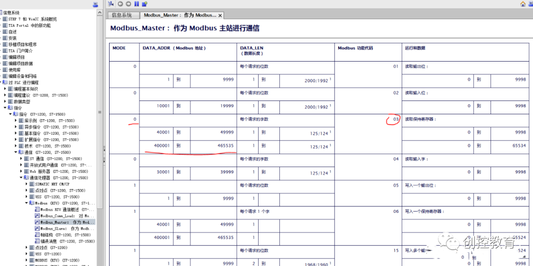
MB_ADDR is the slave address, MODE is the mode, paired with DATA_ADDR to generate standard MODBUS instructions in the background. For example, to implement the instruction frame from the sensor manufacturer:
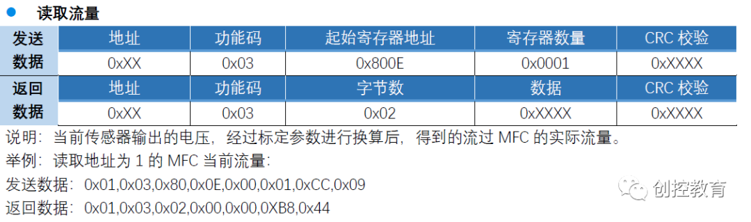
The starting address is 0x800E, which converts to decimal address 32782, and the function code is 0x03.
Through the help of Modbus_Master, I can see that my MODE should select 0, and DATA_ADDR should be filled with: 432782 (in fact, due to whether it starts from 0, this should ultimately be filled with 432783).
Thus, it can be read.
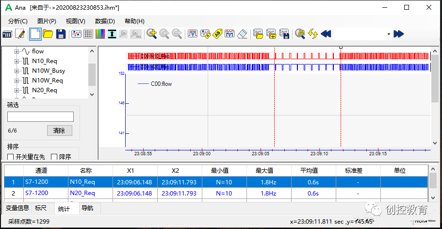
5. Effect of Polling at the Fastest Speed
I used the recording software PLC-Recorder to record the values collected, polling instructions, etc., at a speed of 10ms. From this waveform, it can be seen that the actual polling cycle can reach 100ms (I have two slaves here):
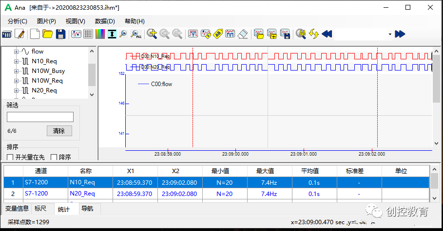
When one of the sensors is powered off, the polling cycle after creating a single station fault is mostly extended to 600ms (because it has to wait for a timeout):
6. How to Diagnose When Communication Fails?
First, use debugging software for convenient testing of the PLC and sensor. For the sensor, you can use the manufacturer’s debugging software in conjunction with a USB to 485 interface for testing to determine communication parameters and status.
For the PLC, some friends used MODBUS slave simulation software for testing (I could not find it), or you can open the cover on the top of the module to check if the sending light is on to determine if the module is enabled. During normal polling, the sending and receiving lights will flash yellow.
(Content sourced from the internet, copyright belongs to the original author)
Disclaimer: If there are copyright issues, please contact for deletion!Neither individuals nor organizations bear any legal responsibility.