Today, let’s talk about the DP/DP Coupler~
If you are familiar with Siemens PLC, especially the 300/400 PLC, you should know or have used this component! Even in this era where industrial Ethernet is so widespread, this component is still used in many factories!
So what is it used for?
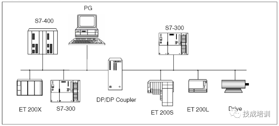
It is actually used to connect two different PROFIBUS-DP networks together for data communication between the two master networks, with a maximum data communication area of 244 bytes input and 244 bytes output.
Connects two different Profibus networks for communication, with different communication rates and station addresses:
A maximum of 16 I/O data exchange areas can be established
The two networks are electrically isolated, so a fault in one segment does not affect the operation of the other segment
Supports DPV1 full mode diagnostics
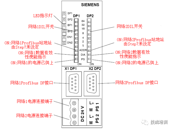
Profibus station addresses can be set via DIL switches, Step 7, or other programming tools
Dual redundant power supply method
For the two segments connected by the DP/DP Coupler, the communication rates can be different, making the DP/DP Coupler very suitable for data communication between two Profibus-DP master systems with different communication rates.
The following will detail how to configure the DP/DP Coupler for communication and program diagnostics in two DP networks using Step7 programming software.
1. Configure DP/DP Coupler as DP Slave in Step7
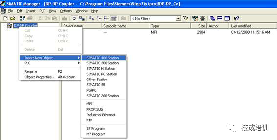
Open the Step7 software, create a new project file named “Gateway as PN IO Proxy”, and insert an S7-400 station under the project, as shown below:
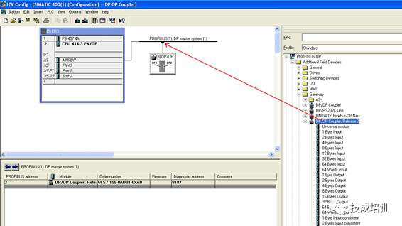
Double-click the “Hardware” of the inserted S7-400 station to open the hardware configuration, and in the hardware configuration interface, insert the rack, power supply PS40, and CPU414-3PN/DP. From the CPU’s MPI/DP interface, create a new Profibus (1) network, with the network protocol as “DP” and the baud rate as “12Mbps”. Drag the DP/DP Coupler from the hardware directory into the Profibus Master, as shown below:
2. Set Profibus Station Address
In the hardware configuration, double-click the DP/DP Coupler to open its properties dialog, and set the station address of the DP/DP Coupler to 3 in the Profibus dialog, as shown below:

3. Set Other Properties of DP/DP Coupler
In the hardware configuration, double-click the DP/DP Coupler to open its properties dialog, switch to the “Parameter Assignment” dialog, and set other properties of the module, as shown below:
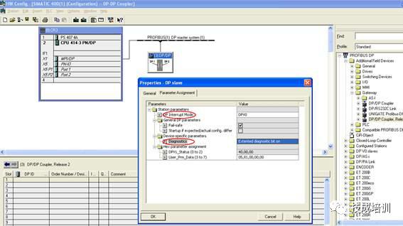
The meanings of each parameter are as follows:
DP Alarm Mode: DPV0 or DPV1, set according to the type of master station system connected
External Diagnostics Enable: ON or OFF
ON: If a diagnostic report is generated in the DP/DP Coupler network (e.g., if the DP connector is pulled from the network), OB82 will be called, the SF indicator will light up, and “Module Error” information will be written to the CPU diagnostic buffer
OFF: If a diagnostic report is generated in the DP/DP Coupler network (e.g., if the DP connector is pulled from the network), OB82 will be called, the SF indicator will not light up, and no information will be written to the CPU diagnostic buffer
Note: If in the module debugging phase, it is recommended to disable the external diagnostic mode, and enable the module external diagnostics after debugging is complete.
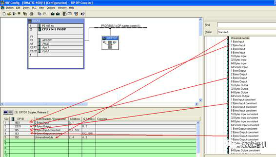
4. Configure Communication Interface Area
In the communication interface area of the DP/DP Coupler module, configure the communication data with network 2, as shown below:
Then configure the DP/DP Coupler in another Profibus master.
1. Configure DP/DP Coupler as DP Slave in Step7
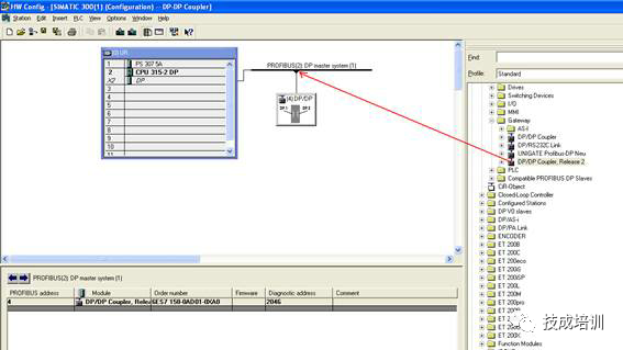
Under the previously created project “Gateway as PN IO Proxy”, insert an S7-300 station, as shown below:

Double-click the “Hardware” of the inserted S7-300 station to open the hardware configuration, and in the hardware configuration interface, insert the rack, power supply PS307, and CPU315-2DP. From the CPU’s integrated DP interface, create a new Profibus (2) network, with the network protocol as “DP”, and the baud rate as “1.5Mbps”. Drag the DP/DP Coupler from the hardware directory into the Profibus Master, as shown below:
2. Set Profibus Station Address
In the hardware configuration, double-click the DP/DP Coupler to open its properties dialog, and set the station address of the DP/DP Coupler to 4 in the Profibus dialog, as shown below:

3. Set Other Properties of DP/DP Coupler
In the hardware configuration, double-click the DP/DP Coupler to open its properties dialog, switch to the “Parameter Assignment” dialog, and set other properties of the module, as shown below:

4. Configure Communication Interface Area
In the communication interface area of the DP/DP Coupler module, configure the communication data with network 1, as shown below:
Note: The data communication areas of network 1 and network 2 must completely correspond (including length and data type), otherwise the module will report a communication fault.
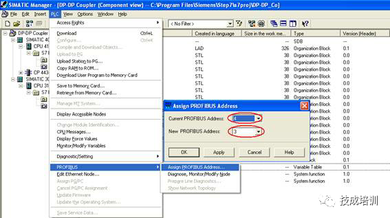
Since the Profibus station address is assigned to the DP/DP Coupler module via Step7, connect the Profibus cable of CP5512 to the DP interfaces of the two networks of the module. Set “Set PG/PC Interface” to “CP5512(PROFIBUS)”, and in Step7, use “PLC->PROFIBUS->Assign PROFIBUS Address…” to assign station addresses to the two networks of the module, as shown below:
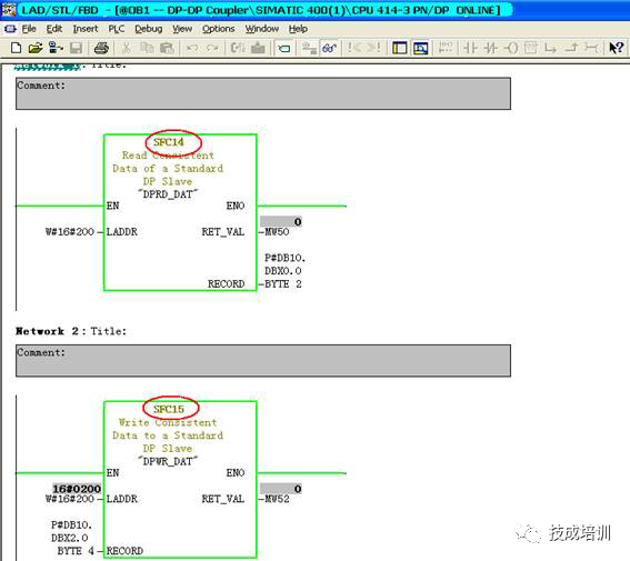
Download the hardware configuration and programs to the CPUs of S7-300 and S7-400, and load OB85-OB87 into the CPUs to prevent the CPUs from stopping due to communication faults. For continuous data areas (configured as “Total length”), it is necessary to call SFC14(DPRD_DAT) and SFC15(DPWR_DAT) in OB1 to ensure that the corresponding data communication between the two networks is completed within a communication cycle, as shown below:
Then, insert a variable monitoring table in both S7-300 and S7-400, and you will see that the communication between the two segments of the DP/DP Coupler module has been established, and the input and output data correspond one-to-one, as shown below:

Complete question bank for the 2021 Electrician Junior Exam (including answers)
Is troubleshooting inverter faults difficult? Just one click!
Can you brush through all electrical exam questions with one click? This magical tool, do you not have it yet?
Which of the five major electrical drawing software (CAD, Eplan, CADe_simu…) would you pick?
Latest electrical version CAD drawing software, with a super detailed installation tutorial!
Latest electrical drawing software EPLAN, with a super detailed installation tutorial!
Common problems for beginners using S7-200 SMART programming software (with download link)
Super comprehensive electrical calculation EXCEL spreadsheet, automatically generated! No need to ask for electrical calculations!
Bluetooth headphones, electrician/PLC introductory books, freely given? Come and claim your electrical gifts!
PLC programming basics: Ladder diagrams and control circuits (with 1164 practical cases of Mitsubishi PLC)
Still can’t understand electrical diagrams? Take away the basics of electrician diagram recognition and simulation software, and quickly get started with theory and practice!
12 free electrician video courses, 10GB of software/e-book materials, and 30 days of free electrician live classes are being given away!