

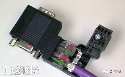
PROFIBUS Physical Wiring and DP Connector Diagram
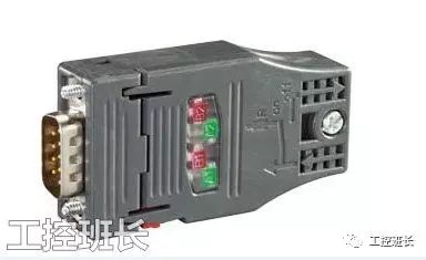
From the diagram, it can be seen that when the switch is turned to “ON”, terminals A1 and B1 are connected to the termination resistor, so only A1 and B1 can be connected at the end of the DP network; otherwise, the termination resistor cannot be connected. When the switch is turned to “OFF”, the termination resistor is disconnected from the data line, and A1 is connected to A2, B1 is connected to B2, forming a series connection of devices on the network.
In normal use, only pins 3 and 8 of the DB9 (male) connector are utilized. To determine whether the hardware connection of the DP network is normal, it is essential to ensure that the data line is securely connected, and the best method for testing is to measure the resistance between pins 3 and 8. If the connection is secure, then when the switch is turned to “ON”, the resistance between 3 and 8 should be 220 ohms, and when the switch is turned to “OFF”, the resistance should be infinite. We can solder two wires to pins 3 and 8 of a DB9 (female) connector, and the other ends of the wires can be soldered to probe tips that can be inserted into a multimeter. When using, insert the two probe tips into the multimeter, set it to the ohm setting, and connect the DB9 (female) connector to one terminal of the DP network. All resistance switches should be set to “OFF”, then start at this terminal and sequentially turn the switches to “ON”, observing the multimeter readings. If it reads 220 ohms, then that node is normal; then turn the switch back to “OFF” and measure the next node. If the resistance at that node is abnormal, it indicates there is a wiring issue at that node. Often, network issues in DP are caused by wiring problems. It is advisable to test the DP cable using the above method before connecting to DP devices to ensure correct hardware connections and improve debugging efficiency.
What is the Role of Adding Termination Resistors in Communication?
The general explanation is that termination resistors are used to eliminate signal reflections in communication cables. During communication, there are two reasons that can cause signal reflections: impedance discontinuity and impedance mismatch. Impedance discontinuity occurs when the signal suddenly encounters a very low or nonexistent impedance at the end of the transmission line, causing a reflection at that point. This principle of signal reflection is similar to the reflection of light when it moves from one medium to another. To eliminate this reflection, a termination resistor equal to the characteristic impedance of the cable must be connected at the end of the cable to ensure impedance continuity. Since the signal transmission in the cable is bidirectional, a termination resistor of the same value can be connected at the other end of the communication cable. Another cause of signal reflection is the impedance mismatch between the transceiver and the transmission cable. This type of reflection is mainly observed when the communication line is idle, leading to data chaos across the entire network. To mitigate the impact of reflected signals on the communication line, noise suppression and adding bias resistors are commonly used. In practical applications, for relatively small reflected signals, the method of adding bias resistors is often used for simplicity and convenience.
Termination Resistors and Bias Resistors
A proper RS-485 network (such as MPI, DP) should use termination resistors and bias resistors. In cases where the network connection is very short, temporary, or for laboratory testing, termination and bias resistors may not be used.
Termination Resistor: A resistor connected in parallel across a pair of communication lines at the two ends of a linear network (the two most distant communication ports). According to transmission line theory, termination resistors can absorb reflected waves on the network, effectively enhancing signal strength. The combined value of the two termination resistors in parallel should be approximately equal to the characteristic impedance of the transmission line at the communication frequency.
Bias Resistor: Bias resistors are used to ensure the relative relationship of A and B signals under complex electrical conditions, ensuring the reliability of the “0” and “1” signals.
Siemens’ PROFIBUS network connectors have built-in termination and bias resistors, which can be conveniently switched on or off with a switch. The termination resistor switch on network terminal connectors must be set to the “ON” position; the termination resistor switch on intermediate site connectors should be set to the “OFF” position.
The values of the termination and bias resistors fully comply with the requirements of Siemens communication ports and PROFIBUS cables.
By closing the termination resistor switch on network connectors, it is very convenient to cut off the signal transmission of the part of the network behind the connector.
When communicating with other devices (using PROFIBUS cables), the other party’s communication port may not be D-SUB9 pin type or the pin definitions may be completely different. For example, Siemens’ MM4x0 frequency converters use terminal wiring forms for the RS-485 communication port, in which case an additional termination resistor needs to be connected. Siemens can provide a standardized external resistor. For other devices, refer to the technical data in the “S7-200 System Manual” for production.
The values of the termination and bias resistors in Siemens network connectors match the characteristic impedance of Siemens PROFIBUS cables, and it is strongly recommended that users use Siemens PROFIBUS cables and network connectors together to avoid many troubles.
Disclaimer: This article is a reprint or adaptation from the internet, and the copyright belongs to the original author. If there are any copyright issues, please contact for removal!
Industrial Control Class Leader QQ: 251087210 (same as personal WeChat)
Scan (long press) to follow Industrial Control Class Leader