The goal of this example is to write a program for the AM22V10 type of Programmable Array Logic (PAL) circuit to simulate a decoder for a seven-segment display.To complete this project, you need to install the following software:WinCUPL which can be downloaded for free from the microchip website at https://www.microchip.com/en-us/development-tool/WinCUPL• The ISIS PROTEUS software from Labcenter.To implement this project, we have 4 binary inputs (counting from 0 to F) and 7 outputs for the display segments, filling in the truth table.A, B, C, D are the inputs, while Sa, Sb, Sc, Sd, Se, Sf, Sg are the outputs for each segment of the display, as shown in the figure: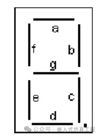 Truth Table:D C B A Sa D C B A Sb D C B A Sc D C B A Sd0 0 0 0 1 0 0 0 0 1 0 0 0 0 1 0 0 0 0 10 0 0 1 0 0 0 0 1 1 0 0 0 1 1 0 0 0 1 00 0 1 0 1 0 0 1 0 1 0 0 1 0 0 0 0 1 0 10 0 1 1 1 0 0 1 1 1 0 0 1 1 1 0 0 1 1 10 1 0 0 0 0 1 0 0 1 0 1 0 0 1 0 1 0 0 00 1 0 1 1 0 1 0 1 0 0 1 0 1 1 0 1 0 1 10 1 1 0 1 0 1 1 0 0 0 1 1 0 1 0 1 1 0 10 1 1 1 1 0 1 1 1 1 0 1 1 1 1 0 1 1 1 01 0 0 0 1 1 0 0 0 1 1 0 0 0 1 1 0 0 0 11 0 0 1 1 1 0 0 1 1 1 0 0 1 1 1 0 0 1 11 0 1 0 1 1 0 1 0 1 1 0 1 0 1 1 0 1 0 01 0 1 1 0 1 0 1 1 0 1 0 1 1 1 1 0 1 1 11 1 0 0 1 1 1 0 0 0 1 1 0 0 0 1 1 0 0 11 1 0 1 0 1 1 0 1 1 1 1 0 1 1 1 1 0 1 11 1 1 0 1 1 1 1 0 0 1 1 1 0 0 1 1 1 0 11 1 1 1 1 1 1 1 1 0 1 1 1 1 0 1 1 1 1 0D C B A Se D C B A Sf D C B A Sg0 0 0 0 1 0 0 0 0 1 0 0 0 0 00 0 0 1 0 0 0 0 1 0 0 0 0 1 00 0 1 0 1 0 0 1 0 0 0 0 1 0 10 0 1 1 0 0 0 1 1 0 0 0 1 1 10 1 0 0 0 0 1 0 0 1 0 1 0 0 10 1 0 1 0 0 1 0 1 1 0 1 0 1 10 1 1 0 1 0 1 1 0 1 0 1 1 0 10 1 1 1 0 0 1 1 1 0 0 1 1 1 01 0 0 0 1 1 0 0 0 1 1 0 0 0 11 0 0 1 0 1 0 0 1 1 1 0 0 1 11 0 1 0 1 1 0 1 0 1 1 0 1 0 11 0 1 1 1 1 0 1 1 1 1 0 1 1 11 1 0 0 1 1 1 0 0 1 1 1 0 0 01 1 0 1 1 1 1 0 1 0 1 1 0 1 11 1 1 0 1 1 1 1 0 1 1 1 1 0 11 1 1 1 1 1 1 1 1 1 1 1 1 1 1Using Karnaugh maps, we derive the following formulas:Sa = C*B + |D*B + D*|A + |C*|A + |D*C*A + D*|C*|BSb = |C*|A + |C*|B + |D*B*A + D*|B*A + |D*|B*|ASc = |B*A + |D*A + D*|C + |D*C + |C*|BSd = |D*B*|A + |D*|C*B + D*|C*A + C*|B*A + D*C*|A + |C*|B*|ASe = B*|A + D*B + D*C + |C*|ASf = D*B + D*|C + C*|A + |B*|A + |D*C*|BSg = D*B + |C*B + D*|C + C*|B*A + |D*C*|ABased on these 7 formulas, we will write the code.Start the WinCUPL program and create a new project
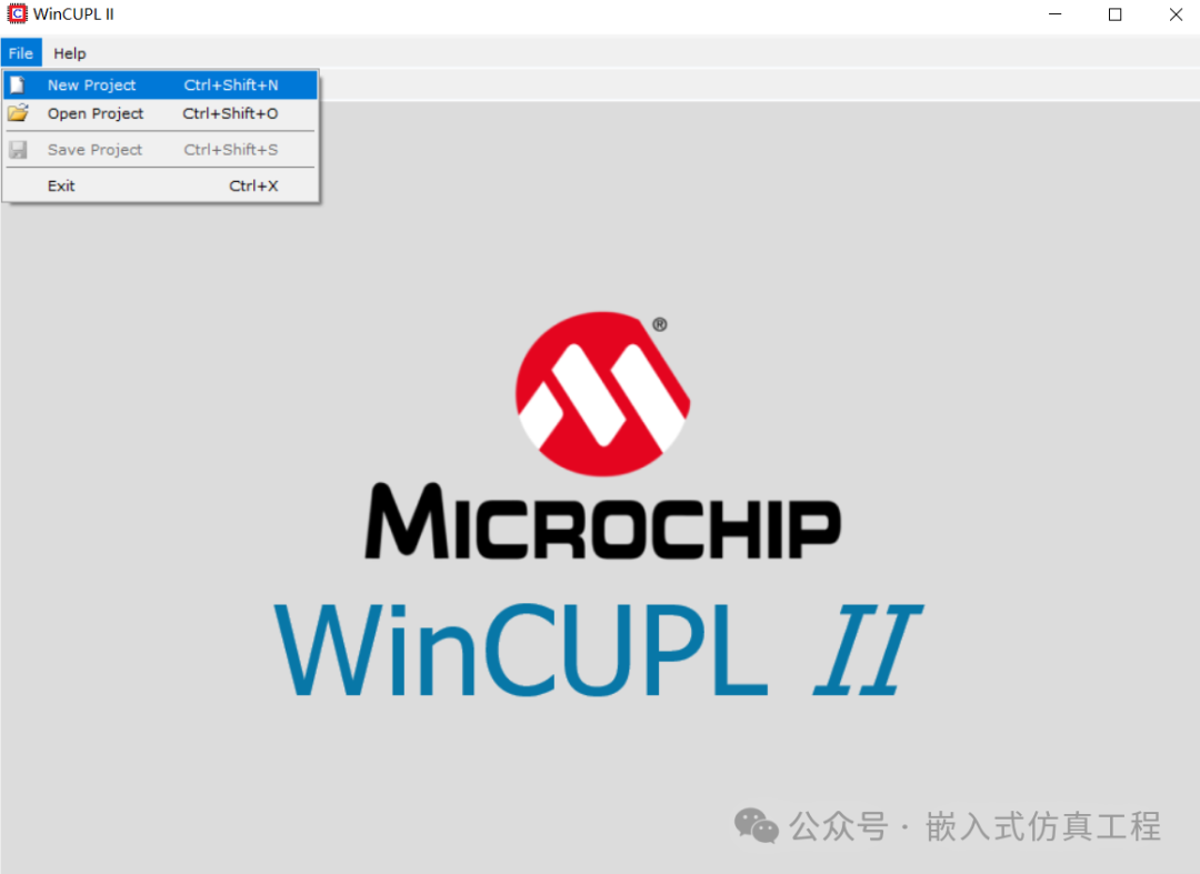 Choose as shown, then click Create Project
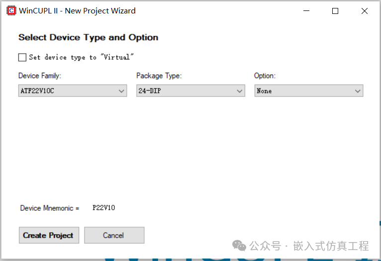 Enter the project name and then click save
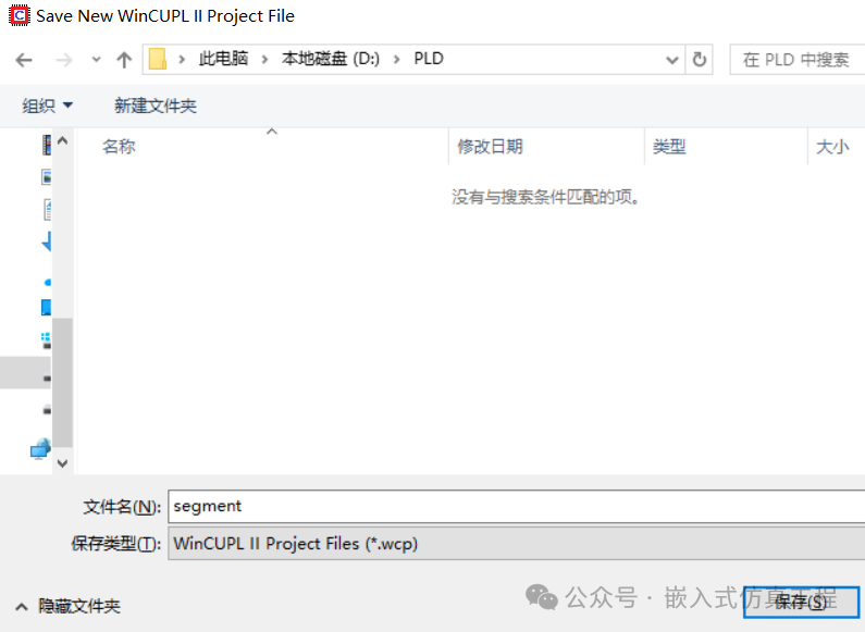 Click on Design File Manager
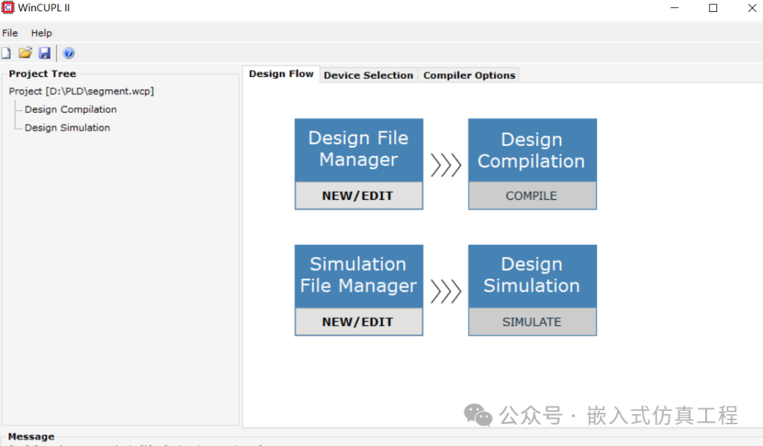 Write the code, save and closeWe must define the pins on the chip that will be used as inputs (input) and associated with the variables. We also need to define the outputs (output).As can be seen, in the formulas, the non-operator “|” becomes “!”, the AND operator “*” becomes “&“, and the OR operator “+” becomes “#“.
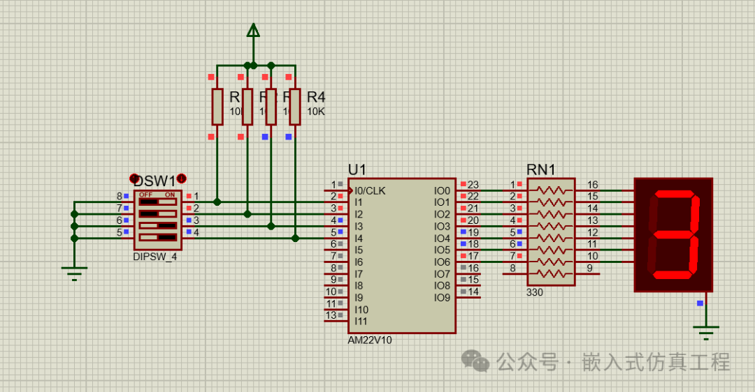 Click on Design Compilation to complete the compilation and generate the .jed file
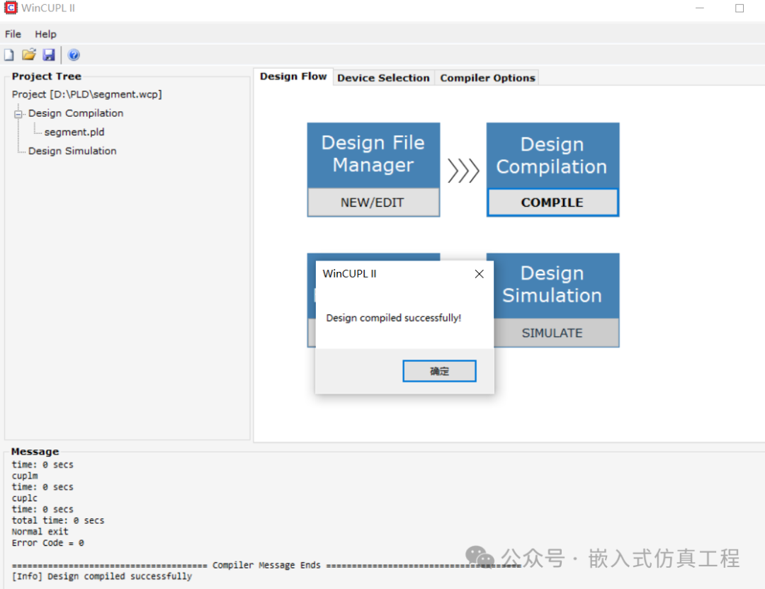 Close WinCUPL and start Proteus. Draw the following circuit diagram:
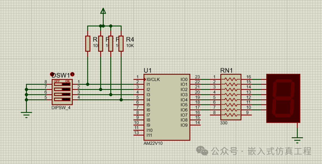 We used 4 10k resistors, 7 330 ohm resistors, 1 seven-segment display, 1 4-button switch group, and 1 PAL AM22V10 circuit. Right-click on the 22v10 chip, edit its properties, and in the area “JEDEC Fuse Map File”: select the path of the previously generated .jed file.
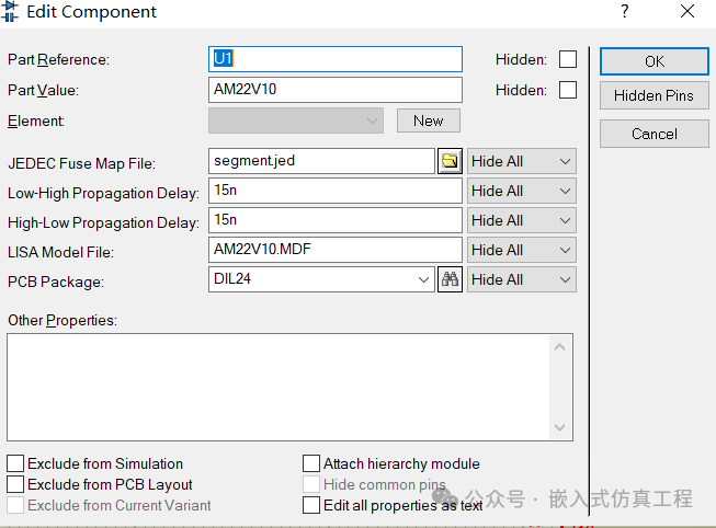 By starting PROTEUS and operating the 4 switches, test the operation of the entire system. You should see the binary code corresponding to the switch positions on the display.
 Welcome to follow (operation reference article: send a message to the public account), click the blue text at the top “Embedded Simulation Project” or long press to identify the QR code to follow
Reply in the public account
2210
You will automatically receive the free simulation project from the example.