Design of a Multifunctional Electronic Scale Based on the 51 Microcontroller
 Editor
Abstract: This paper details the design of a multifunctional electronic scale based on the 51 microcontroller. The electronic scale features basic weighing, tare, overload alarm, weight quality inspection, time display and adjustment, temperature detection and display, data storage, and serial communication. Through hardware circuit design, software programming and debugging, and physical soldering and debugging, the various functions of the electronic scale have been realized, meeting the usage needs in different scenarios.
Keywords: 51 microcontroller; electronic scale; multifunctional design; hardware circuit; software programming
 Editor
1. Introduction
The electronic scale, as a common measuring device, is widely used in various fields such as commerce, industry, and households. With the continuous advancement of technology, people’s requirements for the functions and performance of electronic scales are also increasing. Traditional electronic scales have relatively simple functions, only capable of basic weighing, which cannot meet the diverse needs of modern society. Therefore, designing an electronic scale with multiple functions is of significant practical importance. The 51 microcontroller, as a classic 8-bit microcontroller, has advantages such as low cost, ease of programming, and abundant development resources, making it very suitable for the design of electronic scales. This paper will design a multifunctional electronic scale based on the 51 microcontroller to meet the usage needs in different scenarios.
2. Overall System Design
(1) Design Requirements
- Basic Weighing Function: Able to accurately measure the weight of objects, with a measurement range of 0 – 10Kg and an accuracy of 0.001Kg.
- Tare Function: Can remove the weight of the container, displaying only the net weight of the object.
- Overload Alarm Function: When the weight of the object exceeds the set upper limit, an alarm signal is issued through a buzzer and LED indicator.
- Weight Quality Inspection Function: Can set a standard weight and error range; when the weight of the object exceeds the error range, an alarm signal is issued.
- Time Display and Adjustment Function: Able to display the current time in real-time and adjust the time via buttons.
- Temperature Detection and Display Function: Can detect the ambient temperature and display it on the screen.
- Data Storage and Serial Communication Function: Able to store weighing data in EEPROM and communicate with the host computer via serial port for data transmission and management.
(2) Design Approach
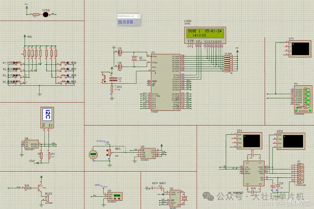
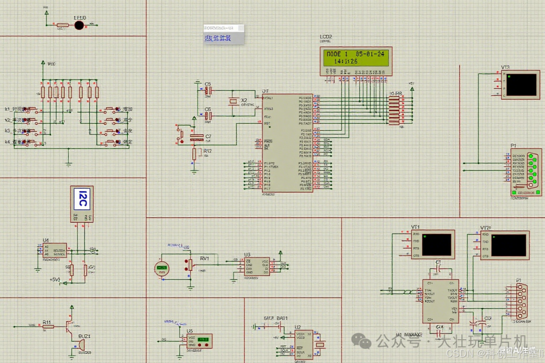
This electronic scale design is mainly divided into two parts: hardware circuit design and software programming debugging. The hardware circuit centers around the 51 microcontroller, connecting weighing sensors, signal conditioning circuits, A/D conversion circuits, display modules, button modules, alarm modules, temperature detection modules, data storage modules, and serial communication modules. The software part uses C language programming to control and manage various functions.
(3) System Composition
The system mainly consists of the following modules:
- Data Acquisition Module: Includes weighing sensors and signal conditioning circuits, responsible for converting the weight of objects into electrical signals and performing amplification and filtering.
- A/D Conversion Module: Converts analog signals into digital signals for processing by the microcontroller.
- Controller Module: Based on the 51 microcontroller, analyzes and processes the collected data, controlling the operation of each module.
- Display Module: Uses an LCD1602 display screen to show the weight, time, temperature, and other information.
- Button Module: Used to set various parameters such as tare, overload alarm limit, standard weight, error range, time adjustment, etc.
- Alarm Module: Includes a buzzer and LED indicator; when overload or weight quality inspection fails, it issues an alarm signal.
- Temperature Detection Module: Uses a temperature sensor to detect ambient temperature and converts the temperature signal into a digital signal for processing by the microcontroller.
- Data Storage Module: Uses an EEPROM chip to store weighing data and setting parameters.
- Serial Communication Module: Implements communication between the electronic scale and the host computer, transmitting weighing data for management and analysis.
3. Hardware Circuit Design
(1) Controller Selection
This design selects the AT89C51 microcontroller as the core controller. The AT89C51 microcontroller is compatible with the 8051 instruction set and has advantages such as low cost and abundant development resources. It has 40 pins, including an 8-bit data bus, a 16-bit address bus, 4 8-bit parallel I/O ports, 2 16-bit timers/counters, and 5 interrupt sources, which can meet the design requirements of this electronic scale.
(2) Weighing Sensor Selection
A bridge-type sensor circuit is selected, and it is recommended to use an H-bridge circuit configuration with an accuracy error of less than ±0.1%. The weighing sensor converts the weight of the object into an electrical signal, which typically has a small output signal that requires signal conditioning.
(3) Signal Conditioning Circuit Design
The signal conditioning circuit includes a differential amplifier and a filter. The differential amplifier is used to amplify the output signal of the weighing sensor, increasing the signal amplitude. The filter is used to eliminate noise and interference from the signal, improving signal quality. In this design, the noise suppression ratio is required to be greater than 60dB.
(4) A/D Conversion Circuit Design
A high-precision A/D conversion chip, such as the HX711, is selected. The HX711 is a 24-bit A/D conversion chip designed specifically for high-precision electronic scales, with high integration, high precision, and strong anti-interference capabilities. It converts analog signals into digital signals and communicates with the microcontroller via serial port.
(5) Display Module Design
An LCD1602 display screen is used, featuring 2 rows and 4 columns of character display with a resolution of 240×128. It can clearly display the weight, time, temperature, and other information of the object, and has advantages such as low power consumption and a large visible area.
(6) Button Module Design
A 4X4 independent key matrix is designed to achieve 16-key input for operations such as weight unit switching, function selection, and parameter setting. The button module detects the button status through scanning and transmits the button information to the microcontroller.
(7) Alarm Module Design
The alarm module includes a buzzer and LED indicator. When overload or weight quality inspection fails, the microcontroller controls the buzzer to sound continuously while the LED indicator flashes to alert the user.
(8) Temperature Detection Module Design
A digital temperature sensor, such as the DS18B20, is selected. The DS18B20 has a single bus interface, high measurement accuracy, and strong anti-interference capabilities. It converts the temperature signal into a digital signal and communicates with the microcontroller via a single bus.
(9) Data Storage Module Design
An EEPROM chip, such as the AT24C02, is used. The AT24C02 has a storage capacity of 2Kbit and communicates with the microcontroller via the I2C bus for storing weighing data and setting parameters.
(10) Serial Communication Module Design
The MAX232 chip is used to convert TTL levels to RS232 levels, enabling serial communication between the electronic scale and the host computer. Through serial communication, weighing data can be transmitted to the host computer for management and analysis, and control commands from the host computer can also be received.
(11) Power Supply System Design
A wide voltage input circuit of 7.4V – 12V is designed to adapt to common lithium batteries or power adapters. A 5V voltage regulator module, such as an LDO chip, is used to achieve single-point power supply, reduce electromagnetic interference, and provide stable operating voltage for each module.
4. Software Design
(1) Main Program Flow
The main program includes initialization configuration, loop detection, and other steps. Initialization configuration includes clock settings, I/O port mode settings, A/D converter initialization, etc. The loop detection part continuously checks keyboard input, sensor signals, and alarm status, executing corresponding operations based on the detection results.
(2) Interrupt Service Program
The interrupt service program includes Timer 0 interrupt and Timer 1 interrupt. The Timer 0 interrupt is used to scan the matrix keyboard, employing a dual verification method of polling and interrupt to improve the accuracy of key detection. The Timer 1 interrupt is used to trigger A/D conversion, configured for an 80us pulse width to ensure the timeliness and accuracy of A/D conversion.
(3) Program Design for Each Functional Module
- Basic Weighing and Tare Function Program Design: Obtain the weight data of the object through A/D conversion. In the tare function, first obtain the weight of the empty container, then subtract it during weighing to get the net weight of the object.
- Overload Alarm Function Program Design: Set the overload alarm threshold. When the weighing data exceeds the threshold, control the buzzer and LED indicator to issue an alarm signal.
- Weight Quality Inspection Function Program Design: Users can set a standard weight and error range. When the weighing data exceeds the error range, an alarm signal is issued.
- Time Display and Adjustment Function Program Design: Use a real-time clock chip, such as the DS1302, to obtain the current time and implement time adjustment via buttons.
- Temperature Detection and Display Function Program Design: Read the data from the temperature sensor and display the ambient temperature on the screen after processing.
- Data Storage and Serial Communication Function Program Design: Store weighing data in EEPROM and send data to the host computer via serial port. At the same time, control commands from the host computer can be received for remote data management.
(4) Calibration Program Design
The three-point calibration method is used, namely empty load calibration, weight calibration with weights, and actual weight comparison calibration. The calibration coefficient is used to convert the A/D conversion count value into actual weight, and the calibration coefficient is stored in EEPROM for use during the next power-up.
5. System Testing and Verification
(1) Static Error Testing
Load standard weights from 0 – 10Kg with a graduation value of 0.5Kg, repeating the measurement 10 times to take the average. The standard deviation must be less than 0.05% to ensure weighing accuracy.
(2) Dynamic Response Testing
Load at a speed of 1Kg/s, recording a response time of less than 200ms; the unloading process should have a lag time of less than 150ms to test the system’s dynamic performance.
(3) Environmental Adaptability Testing
Test the system’s stability and reliability under conditions of temperature ranging from -10℃ to +50℃ (humidity 85% RH without condensation) and vibration testing (10 – 50Hz sine wave scanning, amplitude 0.5mm peak-to-peak).
(4) Function Testing
Conduct comprehensive testing of basic weighing, tare, overload alarm, weight quality inspection, time display and adjustment, temperature detection and display, data storage, and serial communication functions to ensure all functions operate normally.
6. Conclusion
This paper designs a multifunctional electronic scale based on the 51 microcontroller. Through hardware circuit design and software programming debugging, it realizes various functions such as basic weighing, tare, overload alarm, weight quality inspection, time display and adjustment, temperature detection and display, data storage, and serial communication. After system testing and verification, this electronic scale has advantages such as high measurement accuracy, rich functionality, and good stability, capable of meeting usage needs in different scenarios. Additionally, the design cost is controlled within 500 yuan, providing a high cost-performance ratio, suitable for electronic competition practice, hardware development beginners, and DIY electronic device enthusiasts.
References
- Techniques for Using Electronic Scales: Tare, Zeroing, and Clearing Tare
- Upper and Lower Limit Alarm Electronic Scale – Bilibili
- Standards and Inspection Methods for Scales
- Explanation of Electronic Scale Button Functions
- Usage and Maintenance of Electronic Scales!
- What is an Alarm Electronic Scale?
- Design of Electronic Scale Based on 51 Microcontroller
- Getting Started with the 51 Microcontroller: Principles, Programming, and Practical Applications
- Sampling and Tare Function Usage Techniques for Electronic Scales
- 51 Microcontroller Electronic Scale 💡 Accurate Weighing + Overload Alarm
- Electronic Weighing
- Electronic Scale Solutions: Coffee Scale Electronic Scale Design
- Proteus Implementation of Electronic Scale Simulation and Weighing Detection Display