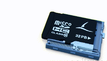
SD cards are familiar to everyone; we have all seen and used them. When inserted, they automatically lock in place, and with another press, they pop out. But what structural principle enables this function?

The card slot mechanism commonly used in mobile devices is simple yet classic. This mechanism is a classic application of springs and “maze slots”:
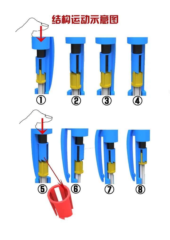
Inside, there is a sliding groove with a separating block at the top. When the card is inserted, it pushes the plastic part down, causing the steel wires with hooks at both ends of the groove to move upwards. When they reach the top, due to the separating block, the steel wires become angled. Once they pass that position, the wires move inward due to elasticity, landing perfectly in the small recess above the separating block, which completes the first step of pressing. When pressed again, the wires are moved to the other side, ensuring they smoothly return to the bottom, thus completing the action of pressing to eject.
This mechanism is a clever application of springs and “maze slots”:
Each turn is designed with steps, ensuring that the pull rod can only move along a specific trajectory and cannot reverse. The principle of this PUSH-PUSH structure is similar to that of a ballpoint pen:
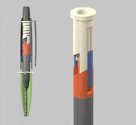
As shown in the image above, this mechanism consists of three parts: the black push rod, the yellow rotating disc, and the blue sliding groove. The red section is a partial screenshot of the groove, and the assisting spring is not shown but is understood to apply an upward force to keep it pressed. When pressure is applied to the push rod, it moves along the groove, forcing the rotating disc down. When the rotating disc disengages from the groove, the pointed features on the head of the push rod create a radial force upon contact with the inclined surface of the rotating disc, causing it to rotate and re-engage with the groove. Pressing the push rod again repeats this action. The engagement between the rotating disc and the groove has two states: one where the disc is embedded in the groove as shown in Figure 8, and another as shown in Figure 4. These two states alternate, representing the retraction and extension of the pen tip.

More videos
-END-
版权说明:感谢每一位作者的辛苦付出与创作,除转载众多无法溯源的文章,我们均在文章中备注了来源。如转载涉及版权等问题,请联系我们删除或支付稿费,非常感谢!


点分享


点点赞


点在看