Practical Guide to Kunlun Tongtai Touch Screen – 002
After installing the Kunlun Tongtai touch screen software, open one as the editing software and the other as the simulation software;
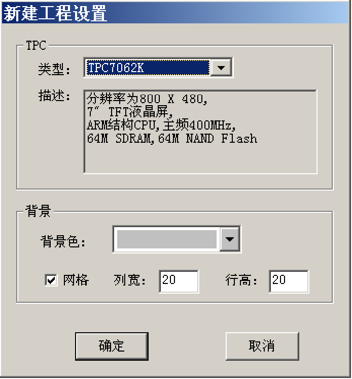
After opening the software, select the corresponding touch screen signal and resolution, and complete the settings directly;
The “Save As” menu item in the file menu pops up the file save window.
In the file name field, enter “TPC Communication Control Project“, and click the “Save“ button to complete the project creation.
This chapter introduces the steps to establish communication with SiemensS7-200 using the MCGS embedded configuration software through examples, with the actual operation addresses being SiemensQ0.0,Q0.1,Q0.2,VW0, and VW2.
1. Device Configuration
(1) Activate the device window in the workbench, double-click with the mouse to enter the device configuration screen, and click the “Open” button in the toolbar to open the “Device Toolbox”, as shown in the figure.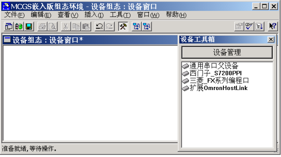
(2) In the device toolbox, double-click on “General Serial Port Parent Device” and “Siemens_S7200PPI” in order (using this communication driver allows direct connection to Siemens Smart 200 series PLC). Add it to the configuration screen window, as shown in the figure.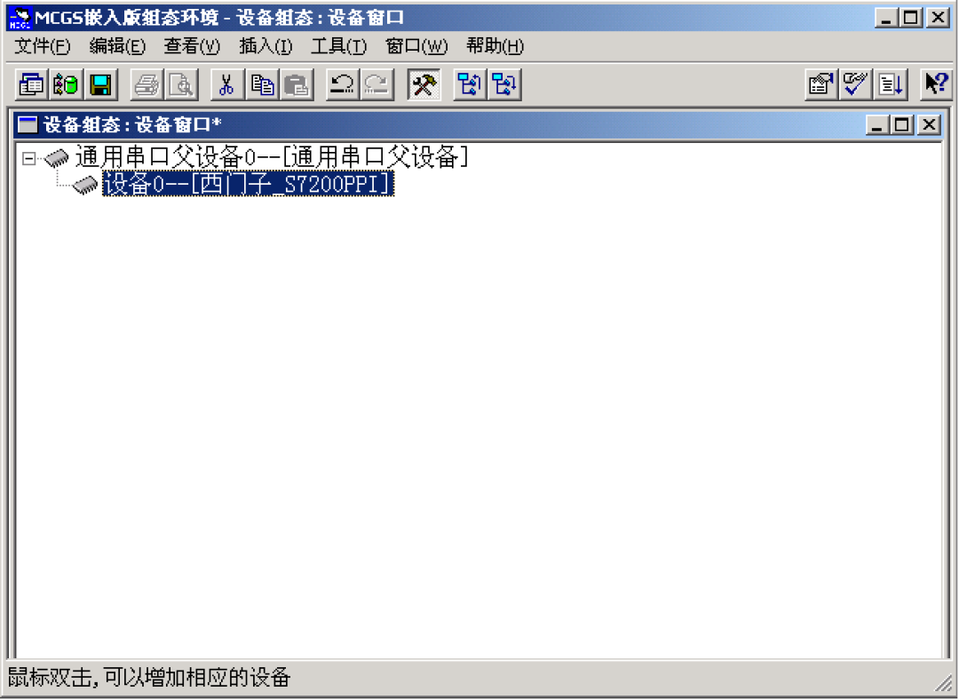
2. Window Configuration
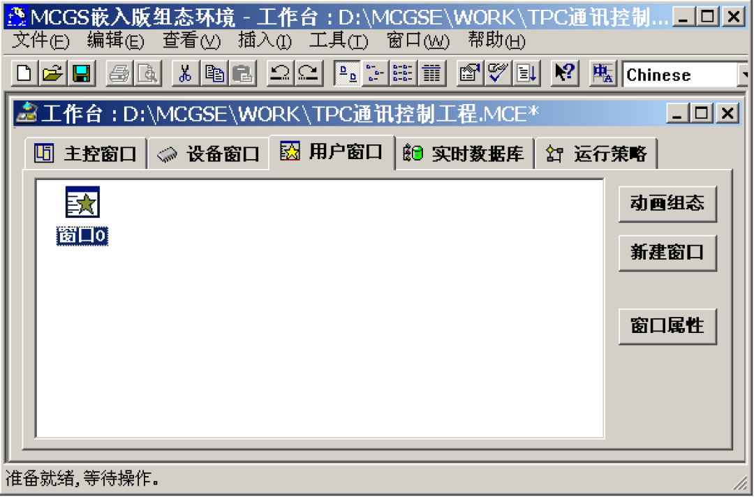
Activate the user window in the workbench, click the “New Window” button to create a new screen “Window 0”. As shown in the figure.
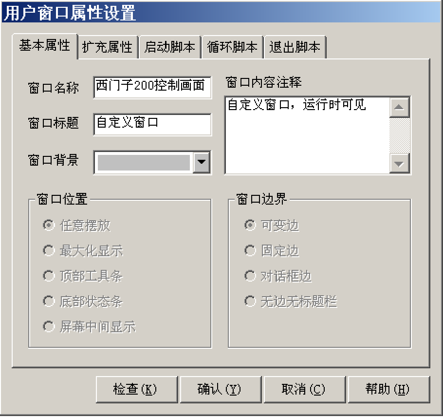
(3) Next, click the “Window Properties” button to pop up the “User Window Property Settings” dialog box. In the basic properties page, change the “Window Name” to “Siemens 200 Control Screen”, and click confirm to save.
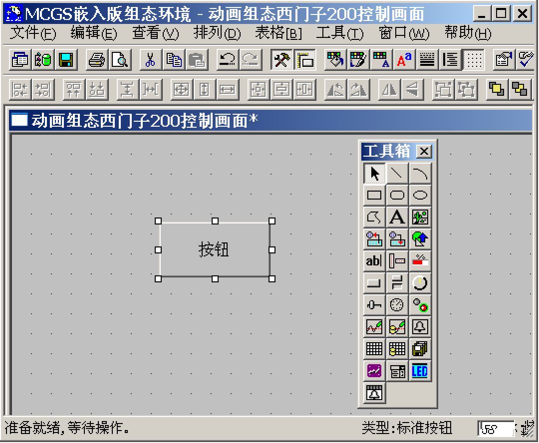
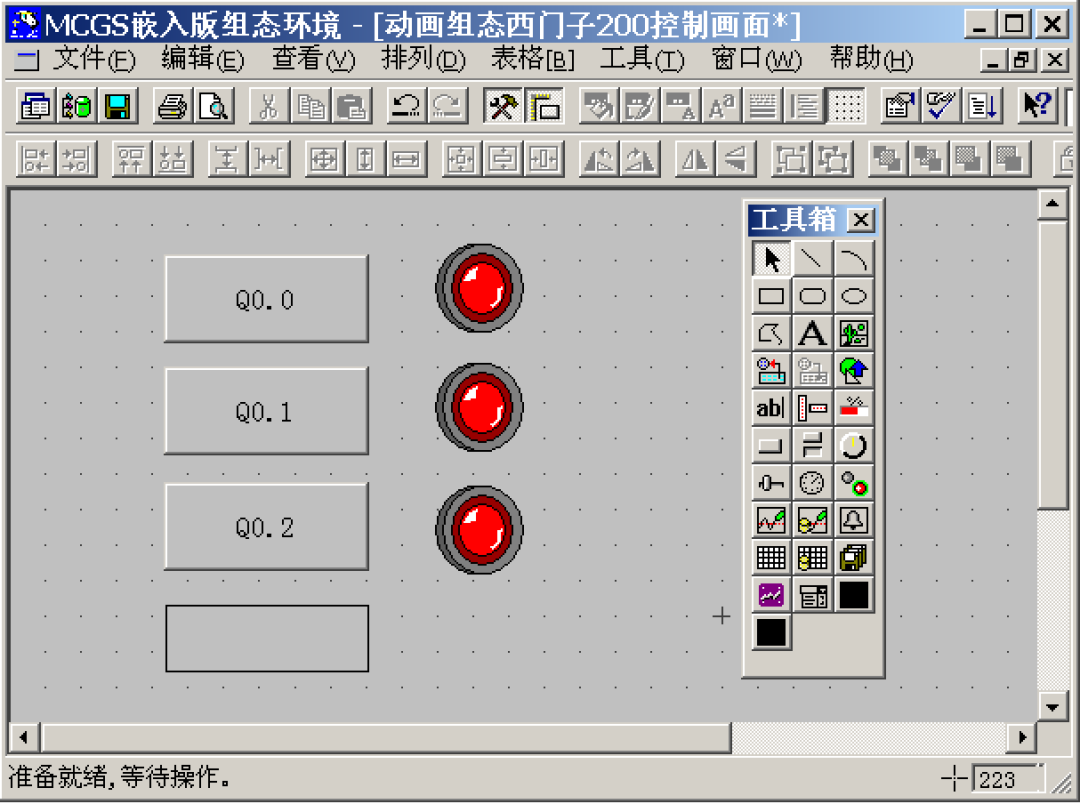
(3) In the user window, double-click to enter the “Animation Configuration Siemens 200 Control Screen”, and click to open the “Toolbox”.
(4) Create Basic Components
① Button: Click “Standard Button” component from the toolbox, hold the left mouse button to drag and drop it to a certain size in the window, then release the left mouse button to draw a button component in the window.
Next, double-click the button to open the “Standard Button Component Property Settings” dialog box, change the “Text” in the basic properties page to Q0.0, and click the confirm button to save,
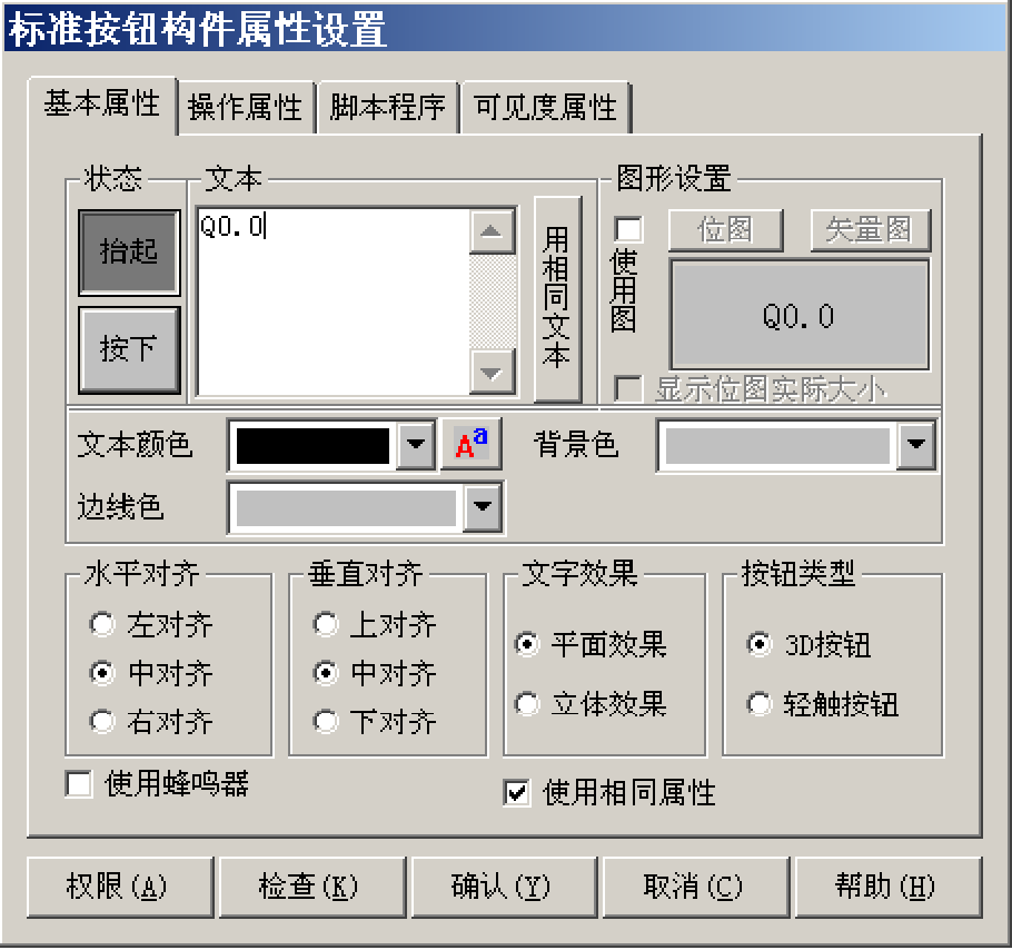
Using the same method, draw the other two buttons, changing the text to Q0.1 and Q0.2, as shown in figure 4-1-8.
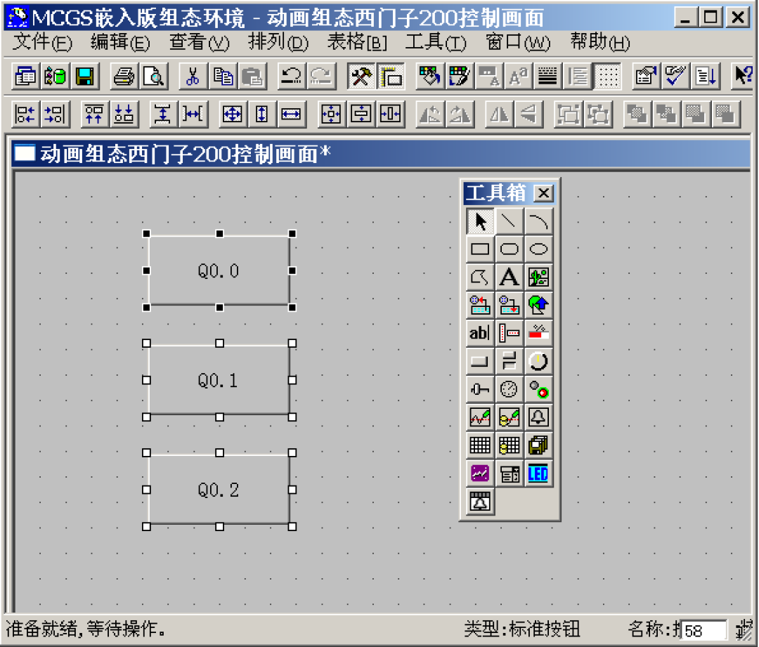
Hold down the ctrl key on the keyboard, then click the left mouse button to select all three buttons, and use the toolbar to align their height, left (right), and vertical spacing.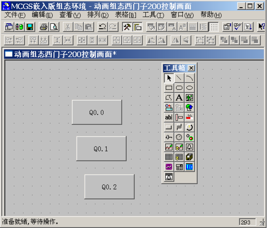
② Indicator Light: Click the “Insert Component” button in the toolbox to open the “Object Component Library Management” dialog box, select a model from the indicator light graphic object library, and click confirm to add it to the window screen. Adjust it to an appropriate size, and use the same method to add two more indicator lights, placing them next to the buttons in the window,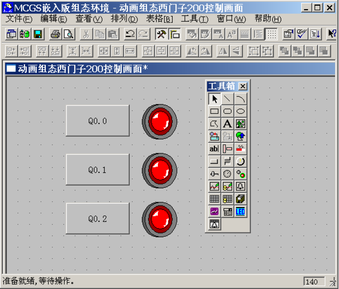
③ Label: Click to select the “Label” component in the toolbox, hold the left mouse button in the window to drag and drop a certain size “Label”, as shown in figure 4-1-11. Then double-click the label to pop up the “Label Animation Configuration Property Settings” dialog box, and in the extended properties page, input VW0 in the “Text Content Input” field, and click confirm,
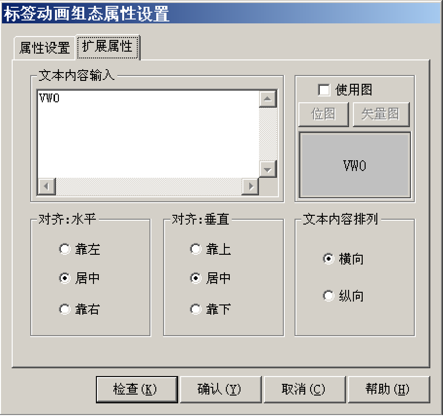
Using the same method, add another label, inputting the text content as VW2
④ Input Box: Click on the “Input Box” component in the toolbox, hold the left mouse button in the window to drag and drop two input boxes of a certain size, placing them next to the VW0 and VW2 labels,
(5) Establish Data Links
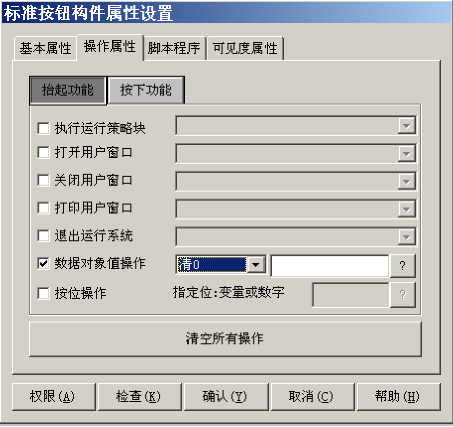
① Button: Double-click the Q0.0 button to pop up the “Standard Button Component Property Settings” dialog box,
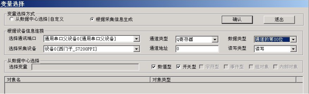
15, in the operation properties page, the default “Lift Function” button is in the pressed state, check “Data Object Value Operation”, select “Clear 0”, and click to pop up the “Variable Selection” dialog box, select “Generate Based on Collection Information”, with the channel type set to “Q Register”, and the channel address as “0”, with the data type set to “Channel Bit 00”, and the read-write type set to “Read/Write”.
After completing the settings, click confirm
When the Q0.0 button is lifted, it will clear the Q0.0 address of Siemens 200 with “Clear 0”,
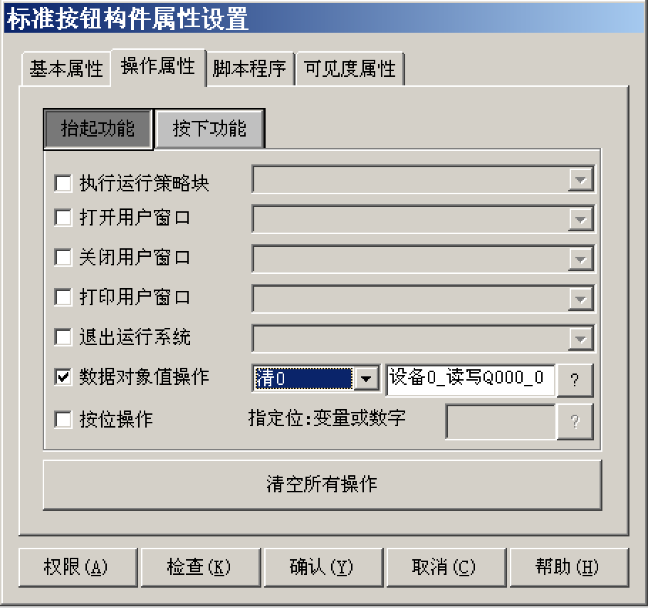
Similarly, click the “Pressed Function” button to set it, data object value operation—> set to 1—> device 0_read-write Q000_0, as shown in the figure
Indicator Light: Double-click the indicator light component next to Q0.0, pop up the “Unit Property Settings” dialog box, in the data object page, click to select the data object “Device 0_read-write Q000_0”, as shown in figure 4-1-19. Similarly, connect the indicator lights next to the Q0.1 and Q0.2 buttons to the variables “Device 0_read-write Q000_1” and “Device 0_read-write Q000_2” respectively.
③ Input Box: Double-click the input box component next to the VW0 label, pop up the “Input Box Component Property Settings” dialog box, in the operation properties page, click to enter the “Variable Selection” dialog box, select “Generate Based on Collection Information”, with the channel type set to “V Register”; channel address as “0”; data type set to “16-bit unsigned binary”; read-write type set to “Read/Write”.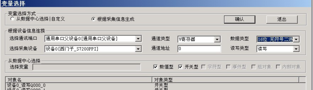
Using the same method, double-click the input box next to the VW2 label for settings, in the operation properties page, select the corresponding data object: channel type set to “V Register”; channel address as “2”; data type set to “16-bit unsigned binary”;
——————————————————————————————–If you have any questions while using, feel free to leave a message. Different questions will be analyzed differently; everyone is welcome to ask questions… Sharing alone is not fun… (*^_^*)