 10G Siemens PLC Resource Collection | Free Download
(Click the above brown word to download the materials)
In practical control projects centered around PLCs, we often rely on the cooperation of touch screens or upper-level computers. This is because we use PLCs for control, primarily to process various analog signals, which are the values we need to monitor, such as pressure, temperature, and flow on the equipment. We then use these detected values to control electric valves, fans, and pumps based on certain conditions. However, we cannot directly see these values from the PLC; to view them, we need to use a touch screen or an industrial computer (which is essentially a computer).
First, it should be noted that this article only explains the general working principle and process of touch screens; it is not a step-by-step guide on how to use a touch screen. I believe understanding its principles and workflow is more important before using and operating the touch screen.
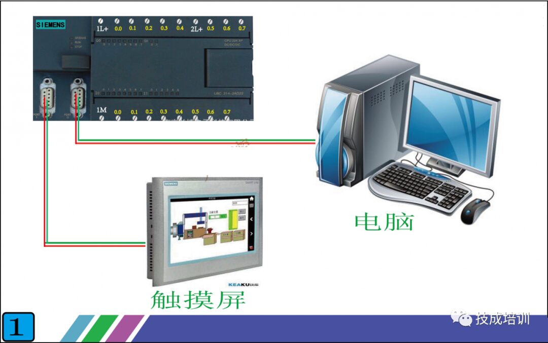
As shown in Figure 1 below, once we connect the touch screen to the PLC, we can see the data we want on the touch screen. In addition to data, we can also control various controlled objects on-site through the touch screen. For example, if we configure a switch on the touch screen, we can start a motor on-site just by clicking the switch on the touch screen.
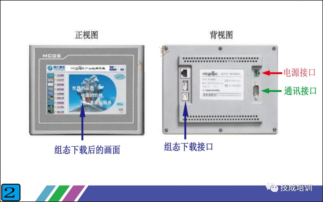
So what is the principle of communication between the touch screen and PLC? Look at Figure 2 below, which shows the front and back of a real touch screen. The front is, of course, the display surface.
We mainly need to look at the back, which has three interfaces:
1. Power Interface: This supplies power to the touch screen, with a voltage mostly at DC24V. The parameter label on the touch screen indicates this.
2. Configuration Download Interface: This is where we use the configuration software provided by the touch screen manufacturer to design the screens and functions we want on the computer, and then download them to the touch screen through this interface. Each touch screen manufacturer has its own software, which is not universal, but that’s okay; the principles are the same. As long as you learn one, you can get familiar with the software interface of the others.
3. Communication Interface: This interface is used for communication with the PLC. The forms of this interface mainly include RS232, RS485, and Ethernet (if you don’t understand what 232 and 485 are, you can refer to my previous articles where they are specifically introduced). It is important to note that the form of this interface must match the form of the PLC’s interface. In Figure 2, the brand of the touch screen is Kunlun Tongtai, and its interface is RS485. Therefore, when connecting to the PLC, the PLC’s interface must also be RS485.
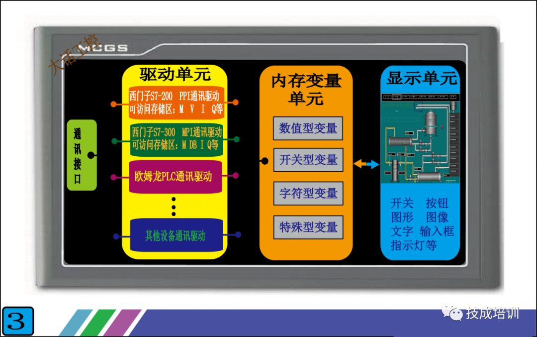
Having looked at the external features of the touch screen, let’s now examine its internal structure. See Figure 3 below, which is a simplified schematic I created of the internal structure of the touch screen. It may not be completely comprehensive, but the important parts are drawn out, and as long as you understand it, that’s fine.
The internal structure of the touch screen can be roughly divided into: communication interface unit, drive unit, memory variable unit, and display unit. Except for the display unit, the other three units are not visible inside the touch screen.
1. Communication Interface Unit: This unit is mainly responsible for sending the data packets packaged by the drive unit to the communication interface at the back of the touch screen, which then sends them to the PLC. We do not need to intervene in this process; the touch screen will complete it automatically. All we need to do is select a driver from the drive unit, which essentially tells the touch screen which driver data packet to send.
2. Drive Unit: This unit stores many communication files for connecting to the PLC, with one file corresponding to one communication protocol (if you don’t understand communication protocols, refer to my previous articles). We call these files drivers. In other words, one driver corresponds to one communication protocol. For example, if the Siemens S7-200 PLC uses the PPI communication protocol, then the touch screen manufacturer will write a file that can communicate with the Siemens S7-200 PLC using the PPI protocol and place it in the drive unit.
For instance, when our touch screen wants to connect with the Siemens 200 PLC, we select the PPI driver in the touch screen. To connect with the Siemens 300 PLC, we select the MPI driver (MPI is the communication protocol for the Siemens 300 PLC). These driver files are pre-written by the touch screen manufacturer, and we can only select them but not modify them. Thus, the more drivers the touch screen has, the broader the range of PLC brands or communication protocols we can choose from. Currently, established touch screen manufacturers have built-in drivers that can cover the commonly used PLCs and communication protocols on the market.
So when we have a touch screen and want to choose a PLC for communication, we must check if there is a driver in the touch screen that can communicate with that PLC.
3. Memory Variable Unit: This unit is also built-in by the touch screen manufacturer. It is essentially a storage area that can hold various types of data, which can be roughly divided into numerical, switch, character, and special types.
For example, if we want to display the water temperature of a boiler on the touch screen, we create a variable in the memory variable unit called “Boiler Water Temperature” (the name can be arbitrary), and select the data type as numerical. Then, the touch screen will automatically allocate a small area in the memory unit for the variable “Boiler Water Temperature”. When the touch screen communicates with the PLC, it will store the water temperature data read from the PLC in this small area, which is the variable “Boiler Water Temperature”. When we need to display multiple data, we just need to create multiple variables. You may still find this a bit confusing; don’t worry, I will explain it systematically according to Figure 4 below, and you will understand.
4. Display Unit: This unit is easy to understand; anything we can see on the touch screen is in the display unit. Using the previous example of “Boiler Water Temperature”, if we want to display the water temperature of the boiler, we just need to drag a display component (this component is available on every touch screen) onto the screen and connect it to the variable “Boiler Water Temperature” that we created above.
Now that we have explained each unit, the most challenging to understand are the drive unit and the memory variable unit. You may still not fully grasp it, but I will clarify it systematically according to Figure 4, and you will be able to understand.
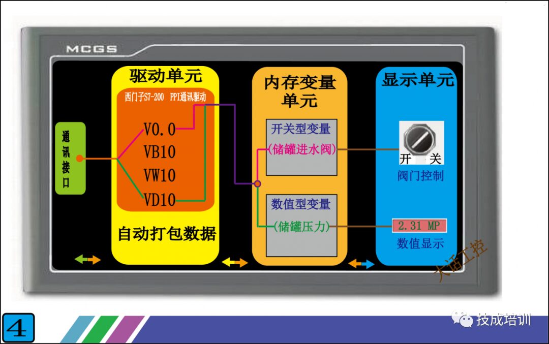
Figure 4 illustrates the functionalities to be achieved: connecting the touch screen with the Siemens S7-200 PLC, 1. Displaying a pressure value from the PLC on the touch screen. 2. Controlling a switch quantity in the PLC through a switch component on the touch screen.
In the first step, we first select the driver in the touch screen. Since we are connecting with the Siemens S7-200 PLC, we need to select the “Siemens S7-200 PPI Communication Driver” from the drive unit. Once the driver is selected, the touch screen will automatically connect the selected driver with the communication interface unit and the memory variable unit. Next, let’s look at the internal structure of this driver (the orange part in Figure 4), which contains many addresses like V0.0, VB10, VW10, etc. These addresses correspond one-to-one with the addresses in the PLC, and the data and status inside are the same as those in the PLC. For example, if the data in PLC’s VD10 is 123.5, then the data in the touch screen driver’s VD10 will also be 123.5. At this point, the touch screen has data, but this data is still not displayed because it has not yet been transferred to the display unit. What should we do?
In the second step, we create a variable in the memory variable unit called “Tank Pressure” and connect it to the VD10 in the drive unit. This way, the variable “Tank Pressure” will have the data 123.5. However, the data still cannot be displayed because it has not been transferred to the display unit.
In the final step, we place a display component with display functionality in the display unit and connect it to the variable “Tank Pressure” in the memory variable unit. This way, we can see the data 123.5. It seems quite complicated, but essentially, all we need to do is connect these units through a newly created variable, and the rest will be completed automatically by the touch screen.
Having understood the workflow of displaying numerical values on the touch screen, controlling a switch quantity becomes straightforward. We just need to place a switch component in the display unit, create a variable, and connect this variable with the drive unit and the display unit. As for how the touch screen transmits this data to the PLC, there is no need to worry; the communication interface unit will handle that for you.
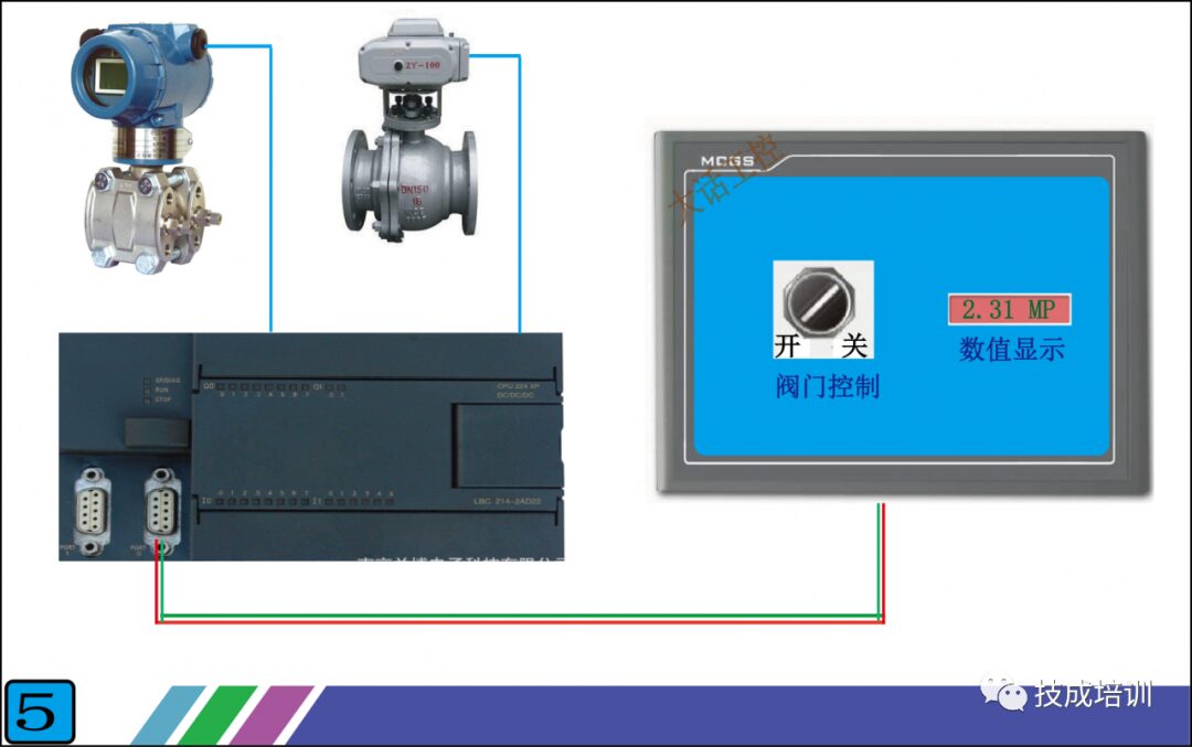
Figure 5 shows the overall connection schematic, which is the most basic combination method. Through this PLC + touch screen combination, we achieve true human-machine dialogue. The data inside the PLC is clear at a glance, and by adding a few switch components on the touch screen, we can reduce the actual use of switches, thereby minimizing the impact of poor contact of actual switch contacts on the control system and improving system stability.
Hurry up and share and save!
Source: Internet
Great Articles:
What is the thickest rope used for lifting, and what does it look like when it snaps?new~
What is the difference between T and L at the back of a car? Finally understood it this time!new~
What kind of company is Lockheed Martin?new~
What does the "ammunition" uranium in nuclear weapons look like?new~
Observe the first-class electromechanical construction practices nationwide, absolutely unique!new~
The largest movable object in the world, a ship's anchor weighs 36 tons, it's like a running mountain.
So this is how condoms are packaged, it seems not easy to understand with 40 mechanical animations...
The deepest diving military nuclear submarine in the world, its hull is made of titanium alloy, and the US still can't produce it.

Material Collection:
Free Download | 545-page manual containing over 45,000 products and solutions new~~ Limited Time Download | 18G Fanuc Robot Video Tutorial (82 lectures in total)! Limited Free | 10G Servo Data Collection! Mitsubishi, Panasonic, Siemens, Yaskawa... what you want, this has it! Free Download | "Industrial Robot Engineering Application Virtual Simulation Tutorial"


Click for more details