The relationship between PLC and inverter is one of inclusion, where both can execute specific commands to control electric motors. The PLC is a programmable hardware for executing programs, while the inverter is one of the devices it can control. However, the PLC’s scope is broader than that of the inverter, enabling it to control more devices across various applications, and it offers superior performance and precision. In contrast, the inverter cannot be programmed and merely alters parameters like frequency and voltage. Its output frequency can be set to a fixed value or dynamically controlled by the PLC. The PLC can be programmed to control electrical components and perform functions and communication tasks.
Communication between PLC and inverter must adhere to the Universal Serial Interface Protocol (USS), following the master-slave communication principle of a serial bus. A master station can connect with up to 31 slave stations, selecting the slave to transmit data based on address characters in the communication message. Slave stations cannot initiate data transmission unless requested by the master, and they cannot exchange information directly.
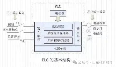
Basic Structure of PLC
The memory of a Programmable Logic Controller (PLC) can be divided into three types: system program memory, user program memory, and working data memory.
1. System Program Memory
The system program memory stores the system programs written by the PLC manufacturer, which are fixed in ROM and cannot be modified by users. The quality of the system program largely determines the performance of the PLC.
It mainly consists of three parts: the system management program, which controls the operation of the PLC; the user instruction interpretation program, which translates the programming language into machine language instructions for the CPU to execute; and standard program modules and system call programs.

2. User Program Memory
The application programs developed according to control requirements are called user programs. The user program memory stores various user programs written in the specified PLC programming language for specific control tasks.
Modern advanced PLCs use flash memory as the user program memory, which can be read and written at any time without needing a backup battery, ensuring data is not lost during power outages.

3. Working Data Memory
Working data memory is used to store working data, including ON/OFF states, numerical data, etc., used in user programs. It includes element image registers and data tables. The element image registers store the ON/OFF states of binary signals, output states, timers, counters, and auxiliary relays, while data tables store variable parameter values and results from A/D conversions.
Basic Structure of Inverter
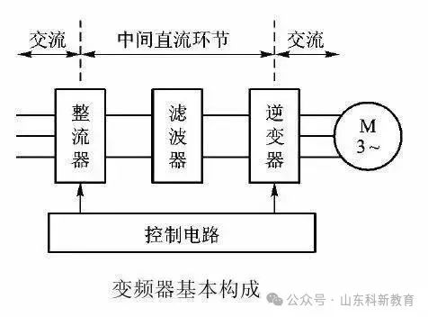
An inverter converts industrial frequency power (50Hz or 60Hz) into various frequencies of AC power, enabling variable speed operation of motors. Its control circuit manages the main circuit, the rectifier circuit converts AC to DC, the DC intermediate circuit smooths the rectified output, and the inverter circuit converts DC back to AC. For vector control inverters that require extensive calculations, a CPU for torque computation may also be needed along with corresponding circuitry.

Three Common Connection Methods Between PLC and Inverter:
1. Using the PLC’s analog output module to control the inverter: The PLC’s analog output module can output 0-5V voltage signals or 4-20mA current signals as the inverter’s analog input signal to control its output frequency. This method is simple but requires selecting a PLC output module that matches the inverter’s input impedance. Additionally, the PLC’s analog output module can be expensive, and voltage division measures must be taken to ensure the inverter adapts to the PLC’s voltage signal range. Wiring should be separated to prevent noise from the main circuit from affecting the control circuit.
2. Using the PLC’s digital output to control the inverter: The PLC’s digital outputs can generally connect directly to the inverter’s digital inputs. This method is straightforward and has strong anti-interference capability. The PLC can control the inverter’s start/stop, forward/reverse, jog, speed, and acceleration/deceleration times, achieving more complex control requirements but only allowing step speed regulation. When connecting using relay contacts, there may be misoperation due to poor contact. When using transistors, factors like the voltage and current capacity of the transistors must be considered to ensure system reliability. Additionally, when designing the inverter’s input signal circuit, improper connections can also cause misoperation. For example, if inductive loads like relays are used, surge currents during relay operation can generate noise that may lead to inverter misoperation, so this should be avoided.
3. Connecting via the RS-485 communication interface: All standard Siemens inverters have an RS-485 serial interface (some also provide an RS-232 interface), designed for industrial applications. A single RS-485 link can connect up to 30 inverters, and based on each inverter’s address or broadcast information, the required inverter can be identified. The link requires a master controller (master station), while the inverters act as subordinate control objects (slave stations).
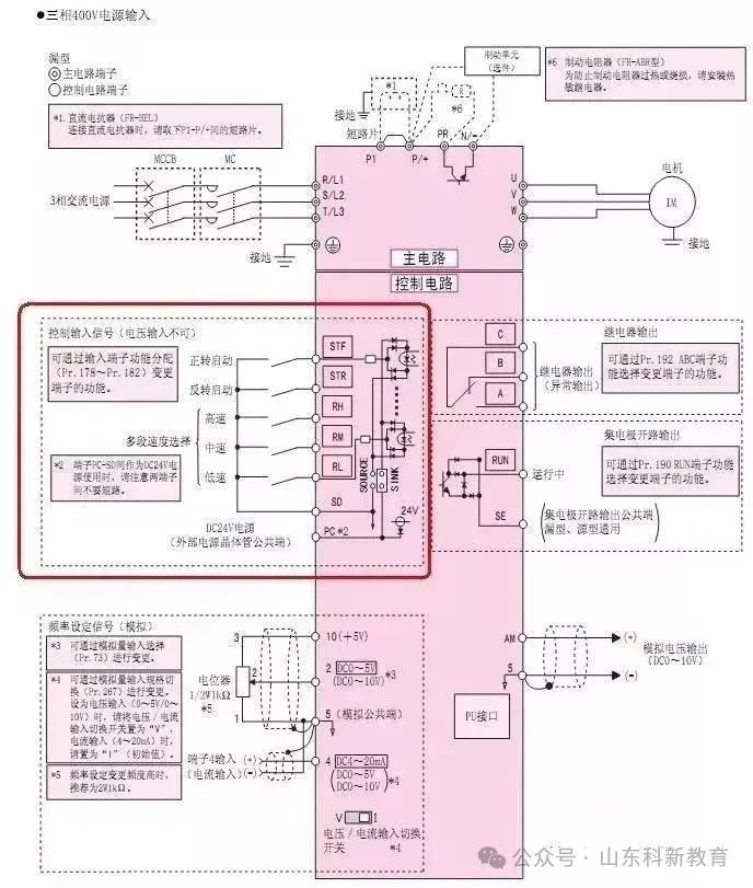
Wiring Diagram for PLC to Control Inverter Motor Direction
1. After wiring according to the diagram, power on to prepare for setting the inverter parameters.
2. Press the “MODE” button to enter parameter setting mode, set Pr.79 to “2”: external operation mode, where the start signal is input from external terminals (STF, STR), and speed adjustment is controlled by external terminals.
3. Continuously press the “MODE” button to exit parameter setting mode.
4. Press the forward button to start the motor in the forward direction.
5. Press the stop button to halt the motor.
6. Press the reverse button to start the motor in reverse.
7. Press the stop button to halt the motor.
8. If the reverse button is pressed while the motor is running forward, it will stop first and then reverse; conversely, if the forward button is pressed while the motor is running in reverse, it will stop first and then run forward.
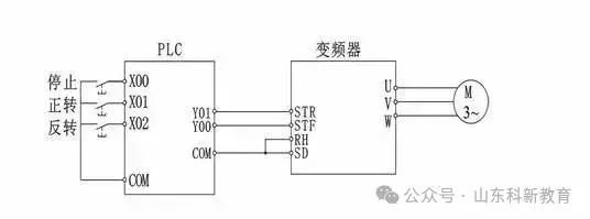
Wiring Diagram for PLC and Inverter

Communication Methods Between PLC and Inverter:
Choosing a day as “International Consumer Rights Day” aims to expand publicity, promote cooperation and interaction among consumer organizations worldwide, raise awareness internationally, and advance consumer protection activities.
1. The PLC’s digital signal controls the inverter: The output points and COM points of the PLC (MR or MT type) directly connect to the inverter’s STF (forward start), RH (high speed), RM (medium speed), RL (low speed), and input SG ports. The PLC can control the inverter’s start, stop, and reset through programming; it can also control combinations of high, medium, and low-speed terminals to achieve multi-speed operation. However, since it uses digital signals for control, the speed curve is not a continuous smooth curve, and precise speed adjustment cannot be achieved.
2. The PLC’s analog signal controls the inverter hardware: The FX1N or FX2N PLC main units can be equipped with a simple FX1N-1DA-BD analog output board; or mixed analog input/output modules like FX0N-3A; or two-output FX2N-2DA; or four-output FX2N-4DA modules. Advantages: Simple and convenient programming, smooth and continuous speed curves, stable operation. Disadvantages: In large-scale production lines, longer control cables, especially when using voltage signals from DA modules, can lead to significant voltage drops, affecting system stability and reliability.
3. PLC controls the inverter using RS-485 communication: This is the most commonly used method, where PLC uses RS serial communication commands for programming. Advantages: Simple hardware, lowest cost, can control up to 32 inverters. Disadvantages: Higher programming workload.
4. PLC controls the inverter using RS-485 Modbus-RTU communication: The new Mitsubishi F700 series inverters utilize the RS-485 terminal to communicate with the PLC using the Modbus-RTU protocol. Advantages: Modbus communication programming is simpler and more convenient than RS-485 without a protocol. Disadvantages: The programming workload remains substantial.
5. PLC controls the inverter using fieldbus: Mitsubishi inverters can be equipped with various communication options, such as the FR-A5NC for CC-Link fieldbus; FR-A5AP (A) for Profibus DP fieldbus; and FR-A5ND for DeviceNet fieldbus. The Mitsubishi FX series PLC has corresponding communication interface modules to connect with these options. Advantages: Fast speed, long distance, high efficiency, stable operation, simple programming, and can connect to many inverters. Disadvantages: Higher cost.
6. Using an expansion memory: Advantages: Low cost, easy to learn and use, reliable performance. Disadvantages: Limited to systems with no more than 8 inverters.

PLC and Inverter Communication Wiring Diagram

Mitsubishi PLC Control of Delta Inverter Case Study
Without external controllers (like PLC), there are three ways to directly operate the inverter:
1. Using buttons on the control panel;
2. Connecting components (like buttons and potentiometers) to terminal connections;
3. Composite operations (setting frequency on the control panel while using connected buttons to control start/stop). For convenience and full utilization of the inverter, PLC can also control the inverter.
Three Basic Ways PLC Controls Inverter:
1. Using digital signals for control;
2. Using analog signals for control;
3. Using RS485 communication for control.

PLC Hardware Connection for Inverter Control Using Digital Signals
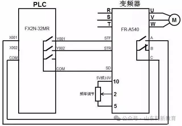
The inverter has many digital terminals, such as forward, reverse, and multi-speed control terminals. When not using PLC, connecting switches to these terminals allows control of the inverter’s forward, reverse, and multi-speed operation. When using PLC to control the inverter with digital signals, the PLC’s digital output terminals must connect to the inverter’s digital input terminals. To monitor certain states of the inverter, the inverter’s digital output terminals can also connect to the PLC’s digital input terminals.
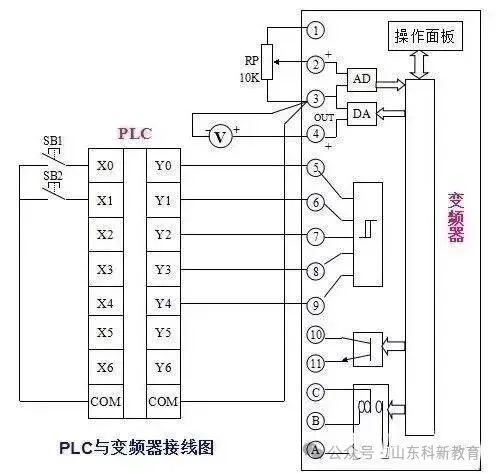
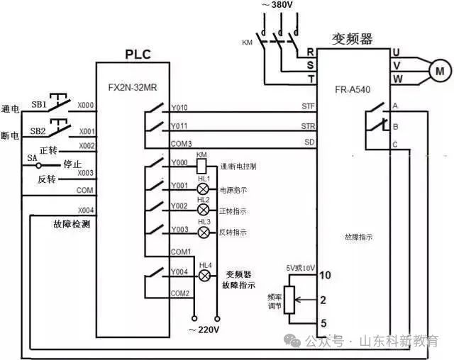
The hardware connection for PLC controlling the inverter with digital signals is shown in the diagram below. When the internal program of the PLC runs and closes the Y001 terminal’s internal contacts, it is equivalent to closing the external switch of the inverter’s STF terminal, making the STF input ON, thus starting the motor in the forward direction. Adjusting the potentiometer connected to terminals 10, 2, and 5 can change the input voltage to terminal 2, thereby altering the frequency of the inverter’s output power and consequently changing the motor speed. If an anomaly occurs within the inverter, the internal contacts between terminals A and C close, equivalent to closing the external switch of the PLC’s X001 terminal, making the X001 input ON.

PLC Hardware Connection for Inverter Control Using Analog Signals
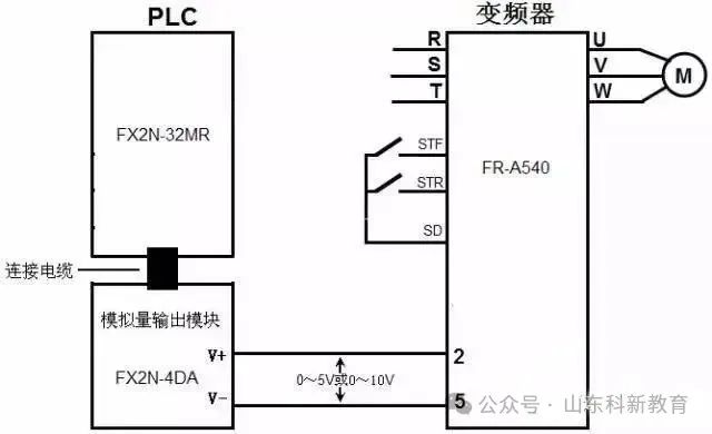
The inverter has voltage and current analog input terminals, and changing the input values of these terminals can alter the motor speed. If these terminals are connected to the PLC’s analog output terminals, the PLC can control the inverter to adjust the motor speed. Analog signals are continuously variable, allowing for smooth speed adjustments without steps.
The hardware connection for PLC controlling the inverter with analog signals is shown in the diagram below. Since the Mitsubishi FX2N-32MR PLC lacks analog output functionality, it requires connecting an analog output module (like FX2N-4DA) and connecting the output terminals of the analog output module to the inverter’s analog input terminals. When the external switch of the inverter’s STF terminal closes, the input becomes ON, thus starting the motor in the forward direction. The digital data generated by the PLC’s internal program is sent to the analog output module (DA module) via a connecting cable, converted into a voltage within the range of 0-5V or 0-10V (analog signal) and sent to the inverter’s terminals 2 and 5, controlling the inverter’s output frequency and subsequently the motor speed. If the voltage output from the DA module to terminals 2 and 5 changes, the inverter’s output frequency will also change, altering the motor speed.
When the PLC controls the inverter’s analog input terminals using analog signals, it can also simultaneously control the inverter’s digital input terminals using digital signals.

PLC Hardware Connection for Inverter Control Using RS485 Communication
When the PLC controls the inverter using digital signals, it occupies many output terminals to connect to the corresponding input terminals of the inverter for controlling forward, reverse, and stop functions. When using analog signals, a DA module is required to control frequency. If PLC uses RS485 communication to control the inverter, only one RS485 communication cable (containing five wires) is needed to send various control and frequency commands directly to the inverter, which will execute the corresponding function control based on the commands received from the PLC through the RS485 communication cable.
RS485 communication is widely adopted in industrial control due to its strong anti-interference capability, with communication distances ranging from dozens to thousands of meters. RS485 communication not only connects two devices for communication but can also connect multiple devices (up to 32 devices in parallel) to form a distributed system for mutual communication.

1. RS485 Communication Port of the Inverter
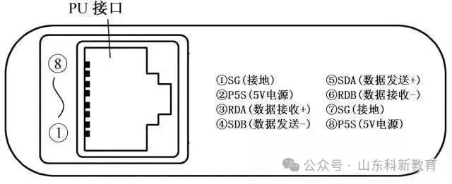
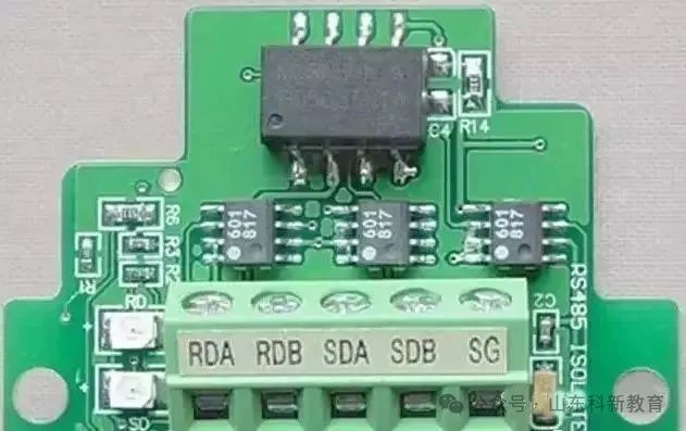
The Mitsubishi FR500 series inverter has a PU port for connecting the operation panel, which can serve as the RS485 communication port. When using RS485 to communicate with other devices, the operation panel connector (RJ45) must be unplugged from the PU port, and one end of the RS485 communication cable should be plugged into the PU port, with the other end connected to the PLC or other devices. The appearance and pin functions of the Mitsubishi FR500 series inverter PU port are shown in the diagram below.
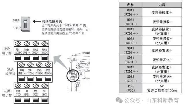
The Mitsubishi FR500 series inverter only has one RS485 communication port (PU port), and the panel operation and RS485 communication cannot occur simultaneously. The Mitsubishi FR700 series inverter, in addition to having a PU port, is also equipped with a separate RS485 communication port (terminal block) specifically for RS485 communication. The appearance and pin functions of the Mitsubishi FR700 series inverter RS485 communication port are shown in the diagram below, where each functional terminal has two connections, one for connecting to one RS485 communication device and the other for connecting to the next device. If there is no subsequent device, the terminal resistor switch should be set to the “100Ω” side.

2. RS485 Communication Port of the PLC
Mitsubishi FX PLC generally does not come with an RS485 communication port. To communicate with the inverter via RS485, the FX2N-485BD communication board must be installed on the PLC. The appearance and terminals of the 485BD communication board are shown in the diagram below (a), and the installation method is shown in the diagram below (b).
(a) Appearance
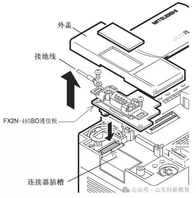
(b) Installation Method

3. RS485 Communication Connection Between Inverter and PLC
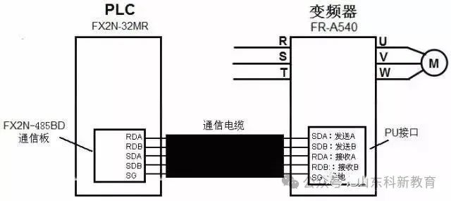
(1) RS485 Communication Connection of a Single Inverter and PLC
The RS485 communication connection of a single inverter and PLC is shown in the diagram below. When connecting, the sending terminal (+-) of one device should connect to the receiving terminal (+-) of the other device, and the receiving terminal (+-) should connect to the sending terminal (+-) of the other device.
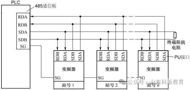
(2) RS485 Communication Connection of Multiple Inverters and PLC: The RS485 communication connection of multiple inverters and PLC is shown in the diagram below, allowing one PLC to control the operation of multiple inverters.


Circuit, Program, and Parameter Settings for PLC Control of Inverter-Driven Motor Direction

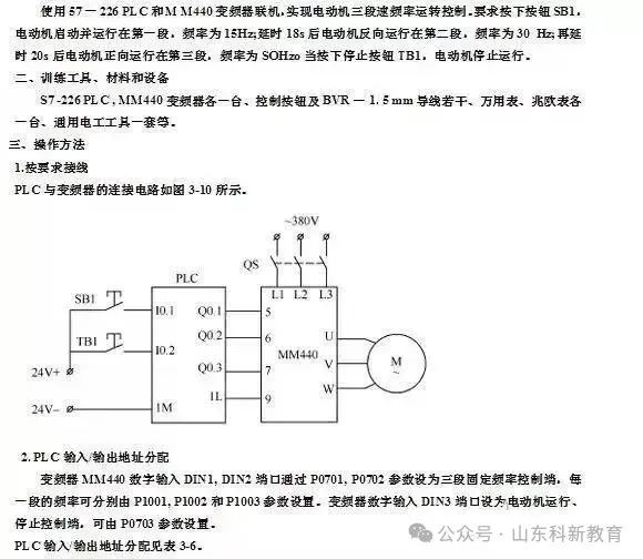
1. Wiring Diagram for PLC and Inverter Hardware Connection
The wiring diagram for PLC controlling the inverter-driven motor direction is shown below.

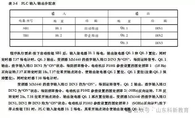
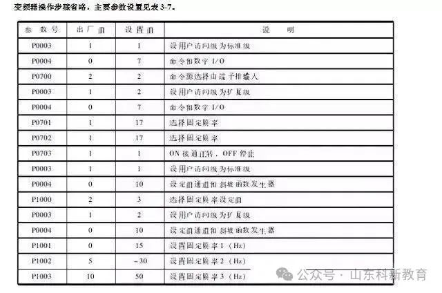
2. Parameter Settings for Inverter
When using PLC to control the inverter, relevant parameter settings must be configured, as detailed in the table below.

3. Writing PLC Control Program
After the relevant parameters of the inverter are set, the corresponding PLC control program must be written using programming software and downloaded to the PLC. The PLC program for controlling the inverter to drive the motor in forward and reverse directions is shown in the diagram below.

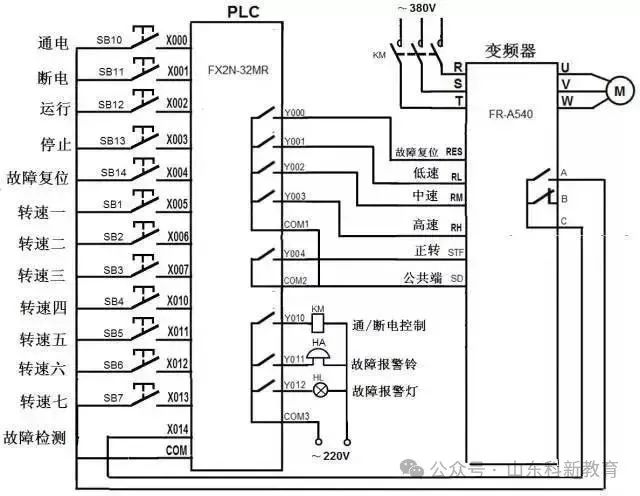
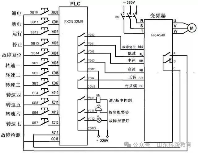
Circuit, Program, and Parameter Settings for PLC Control of Inverter-Driven Motor Multi-Speed Operation
The inverter can provide continuous speed control or multi-speed control. The FR-500 series inverter has three control terminals: RH (high speed), RM (medium speed), and RL (low speed). By combining these three terminals’ inputs, seven-speed control can be achieved. If the PLC’s output terminals are connected to these terminals of the inverter, the PLC can control the inverter to drive the motor at multiple speeds.
1. Wiring Diagram for PLC and Inverter Hardware Connection
The wiring diagram for PLC controlling the inverter-driven motor multi-speed operation is shown below.

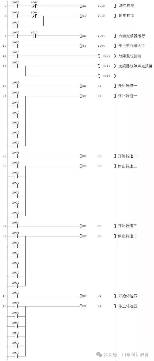
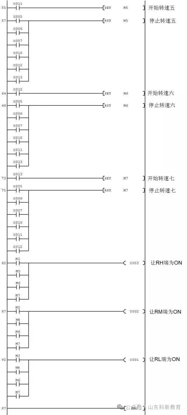
2. Writing PLC Control Program
The PLC program for controlling the inverter-driven motor multi-speed operation using digital signals is shown in the diagram below.

Source: This article is reprinted from the internet, and the copyright belongs to the original author. If there are any copyright issues, please contact us promptly for deletion. Thank you!

Scan to Follow
WeChat ID|13615417996
Follow the left QR code to get free access to
[Siemens Data Collection]