Solar energy, as a clean and renewable energy source, has been a research hotspot for its efficient utilization. This article will detail the hardware design, software implementation, and key technical points of a solar tracking system based on the 51 microcontroller. The system detects light intensity using a photoresistor and controls a stepper motor to adjust the angle of the solar panel, maximizing energy collection. The system includes a sensor module, control module, motor drive module, and display module, featuring an automatic/manual dual-mode switching function.
System Overview and Design Principles
The solar tracking system (also known as a solar tracking system) is a photovoltaic power generation technology that adjusts the angle of the solar panel in real-time to always face the sun, which can increase solar conversion efficiency by 30%-40% (Design and Implementation of a Solar Tracking System Based on the 51 Microcontroller). This design uses the STC89C52 microcontroller as the control core, combined with a photoresistor array and dual-axis stepper motor to achieve automatic tracking in two axes (horizontal X-axis and vertical Y-axis).
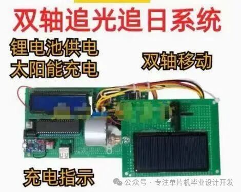
Dual-axis tracking system hardware device, including solar panel, stepper motor, and lithium battery power supply module
The system operates as follows:
- Light Intensity Detection: Four photoresistors detect light intensity in the up, down, left, and right directions, converting the analog signals to digital signals through the PCF8591 ADC module.
- Data Processing: The microcontroller compares the light intensity values from each direction and calculates the deviation of the sun’s position.
- Motor Control: The ULN2003 drives the stepper motor to adjust the angle of the solar panel, ensuring that the direction with the highest light intensity is always perpendicular to the panel surface (51 microcontroller dual-axis solar tracking system with ULN2003 stepper motor).
- Mode Switching: Supports both automatic tracking and manual button control modes.
Detailed Hardware Design
Core Module Selection
-
Microcontroller Module: The STC89C52 is used, featuring 8KB Flash and 512B RAM, fully meeting system requirements. The minimum system includes an 11.0592MHz crystal oscillator, a 10K reset circuit, and a power filtering circuit.
-
Sensor Module:
- Photoresistor: GL5528, bright resistance 5-10KΩ, dark resistance over 1MΩ
- ADC Conversion: PCF8591, I2C interface, 8-bit resolution, four-channel input (Design of an Energy-saving Photovoltaic Solar Tracking System Based on the 51 Microcontroller)
-
Motor Drive Module:
- Stepper Motor: 28BYJ-48-5V, five-wire four-phase, reduction ratio 1:64
- Driver Chip: ULN2003, maximum drive current 500mA
-
Power Module:
- 18650 lithium battery (3.7V) with TP4056 charging management
- Solar panel output 5V/2W
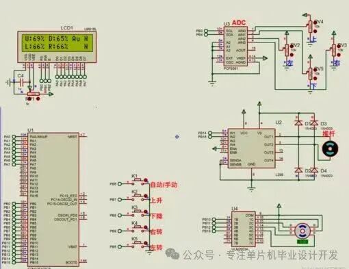
System hardware circuit schematic, including the minimum microcontroller system, ADC circuit, and motor drive circuit
Key Circuit Design
Photoresistor Detection Circuit uses the voltage divider principle, with the photoresistor in series with a 10KΩ fixed resistor, where the voltage change reflects light intensity:
Vout = Vcc * (Rfixed / (Rfixed + Rlight))
Motor Drive Circuit uses the ULN2003 Darlington array, with the microcontroller IO port outputting phase signals to control the motor rotation direction:
// Stepper motor phase tableconst unsigned char phase[] =
{0x09,0x08,0x0C,0x04,0x06,0x02,0x03,0x01};
Software Design and Implementation
Main Program Framework
The system software adopts a modular design, mainly including initialization, data acquisition, position calculation, and motor control. The main program flow is as follows:
C
void main() { System_Init(); // System initialization LCD_Init(); // LCD initialization ADC_Init(); // ADC initialization Motor_Init(); // Motor initialization while(1) { if(Auto_Mode) { // Automatic mode Light_Read(); // Read four light intensities Position_Calc(); // Calculate position deviation Motor_Adjust(); // Adjust motor position } else { // Manual mode Key_Scan(); // Scan keys Manual_Ctrl(); // Manual control } Display(); // Refresh display }}
Key Algorithm Implementation
Light Intensity Collection and Processing: The PCF8591 cyclically collects four light intensities, using a sliding average filter to eliminate noise
// Read ADC value (channel 0-3)unsigned char ADC_Read(unsigned char ch)
{ I2C_Start(); I2C_SendByte(0x90); // PCF8591 write address I2C_SendByte(0x40|ch); // Control word: enable ADC, select channel I2C_Start(); I2C_SendByte(0x91); // PCF8591 read address value = I2C_RecvByte(); // Read ADC value I2C_Stop(); return value;}
Position Control Algorithm: Uses the difference comparison method, triggering motor action when the light intensity difference in a certain direction exceeds a threshold
void Motor_Adjust() { if(Up_Down_diff > THRESHOLD) { // Up-down light intensity difference exceeds threshold if(Up_Value > Down_Value) Motor_Up(Steps); // Rotate up else Motor_Down(Steps); // Rotate down } if(Left_Right_diff > THRESHOLD) { // Left-right light intensity difference exceeds threshold if(Left_Value > Right_Value) Motor_Left(Steps); // Rotate left else Motor_Right(Steps); // Rotate right }}
Stepper Motor Control: Uses a four-phase eight-step method to improve rotation accuracy
// Stepper motor clockwise (one pulse)void Motor_StepCW() { static unsigned char index = 0; P1 = phase[index]; // Output phase signal index = (index+1)%8;// Phase index loop Delay_ms(2); // Pulse interval}// Stepper motor counterclockwisevoid Motor_StepCCW() { static unsigned char index = 0; P1 = phase[7-index];// Reverse phase sequence index = (index+1)%8; Delay_ms(2);}
System Optimization and Expansion
Energy-saving Optimization Strategies
- Intermittent Working Mode: When light intensity changes are less than 5%, the system enters sleep mode, waking up every 5 minutes for detection (Design of an Energy-saving Photovoltaic Solar Tracking System Based on the 51 Microcontroller).
- Dynamic Threshold Adjustment: Automatically adjusts action thresholds based on ambient light intensity to avoid frequent fine-tuning.
- Low Power Design: Uses the STC15W series low-power microcontroller, with idle mode current <1mA.
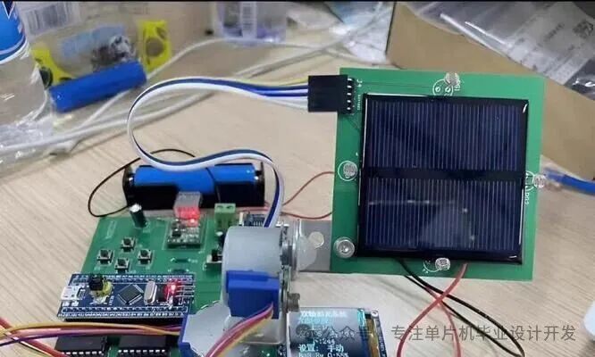
Prototype physical image of the system, including solar panel, control circuit, and mechanical transmission structure
Complete Source Code Example
The following is the core control code of the system, including detailed comments:
/** * @file main.c * @brief Main program for the solar tracking system based on the 51 microcontroller * @details Function: Four-channel light intensity detection, dual-axis motor control, automatic/manual mode switching * @author techmaker */#include <reg52.h>#include “i2c.h” // I2C communication library#include “lcd1602.h”// LCD driver#define THRESHOLD 20 // Light intensity action threshold// Pin definitionssbit K1 = P3^0; // Mode switch buttonsbit K2 = P3^1; // Manual upsbit K3 = P3^2; // Manual downsbit K4 = P3^3; // Manual leftsbit K5 = P3^4; // Manual right// Global variablesunsigned char Auto_Mode = 1; // Working mode flagunsigned char Up_Value, Down_Value, Left_Value, Right_Value; // Four light intensity values/** * @brief System initialization */void System_Init() { PCF8591_Init(); // Initialize ADC Motor_Init(); // Motor initialization EA = 1; // Enable global interrupt // Other peripheral initializations…}/** * @brief Read four light intensity values */void Light_Read() { Up_Value = ADC_Read(0); // Read upper photoresistor Down_Value = ADC_Read(1); // Read lower photoresistor Left_Value = ADC_Read(2); // Read left photoresistor Right_Value = ADC_Read(3); // Read right photoresistor}/** * @brief Main loop */void main() { System_Init(); while(1) { Light_Read(); // Read light intensity if(K1 == 0) { // Mode switch Delay_ms(10); if(K1 == 0) { Auto_Mode = !Auto_Mode; while(!K1); // Wait for key release } } if(Auto_Mode) Auto_Track(); // Automatic tracking else Manual_Ctrl(); // Manual control Display_Info(); // Display system information }}/** * @brief Automatic tracking function */void Auto_Track() { // Calculate up-down light intensity difference if(abs(Up_Value – Down_Value) > THRESHOLD) { if(Up_Value > Down_Value) Motor_Up(5); // Move up 5 steps else Motor_Down(5); // Move down 5 steps } // Calculate left-right light intensity difference if(abs(Left_Value – Right_Value) > THRESHOLD) { if(Left_Value > Right_Value) Motor_Left(5); else Motor_Right(5); }}
Conclusion and Outlook
This system achieves dual-axis automatic tracking of the solar panel using the 51 microcontroller, with hardware costs controlled under 50 yuan, suitable for teaching demonstrations and small to medium power solar applications. Tests show that compared to fixed installations, it can increase power generation efficiency by over 35% (Design of an Automatic Solar Tracking Control System Based on the 51 Microcontroller).
If you need materials or have suggestions, please contact me privately ❤️