When faced with a brand new PLC, do you feel like you are confronting a silent black box? Once the program is loaded, it seems to act according to your will, which appears magical.
But do you know what kind of endless “scan-decision-execute” cycle is taking place inside the moment it is powered on?
Many beginners are obsessed with learning instructions and writing programs, but they overlook the most fundamental cornerstone — how does a PLC actually work? Understanding this is essential for progressing from a “programmer” to an “architect,” truly mastering the heart of industrial automation.
Today, we will not write a single line of code; we will do just one thing:deconstruct the timing and gain insight into its essence.
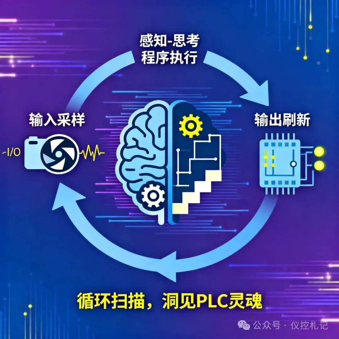
The Core Secret: The Scanning Cycle Work System
First, forget about the “event-driven” nature of your computer programs. The essence of a PLC is that it is a machine with an extremely regular work schedule. Its life consists of one uninterrupted scanning cycle after another.
In each cycle, it precisely and repeatedly executes three core steps:Read Inputs → Execute Program → Update Outputs
This may seem simple? Let’s dive deeper and see what precision and wisdom lie beneath the surface.
Act One: Input Sampling — The Moment the Shutter Clicks
At the start of each scanning cycle, the PLC performs an unexpected action for beginners:
It takes a snapshot of all input points (I0.0, I0.1…) at lightning speed, capturing their current on/off states and storing them in a memory area called the “Input Image Table”.
Remember this crucial detail: Throughout the subsequent scanning cycle, regardless of how external input signals fluctuate, blink, or change, the data in the “Input Image Table” remains frozen and unchanged.
Why? Imagine if you were solving a complex math problem, but the numbers in the question kept changing; you would never arrive at the correct answer. The PLC operates similarly; it requires a stable and consistent input snapshot as the sole basis for logical operations in this cycle.
This is the first cornerstone of the reliability of PLC’s working logic.
Act Two: Program Execution — High-Speed Computation of the Brain
Now, the PLC’s CPU transforms into the most meticulous accountant. It takes the “input snapshot” (Input Image Table) captured in the previous phase and begins to perform high-speed calculations line by line, logically, starting from the first instruction of the user program.
It traverses your entire ladder diagram or statement table:<span>"If I0.0 is on and I0.1 is off, then let M0.0 be on..."</span><span>"If M0.0 is on, then timer T37 starts timing..."</span>
The key point is: At this stage, all calculation results are merely intermediate variables. They will update the states of “internal auxiliary relays (M)”, “timers (T)”, “counters (C)” and other soft components in real-time, but will never affect the physical state of the actual output points (Q).
The program execution phase is a “sandbox simulation” that occurs internally within the PLC, isolated from the outside world. The results of this simulation are carefully recorded in the “Output Image Table”.
Act Three: Output Refresh — The Thunderous Execution
When the last line of the program has been executed, the simulation ends. The moment for real action has arrived!
The PLC will copy the final results calculated during the entire scanning cycle from the “Output Image Table” to the actual physical output modules all at once and synchronously.
Thus, Q0.0 is energized, the contactor pulls in; Q0.1 is off, the indicator light goes out. At this moment, the external world truly perceives the PLC’s will.
The moment the output refresh is completed, a scanning cycle comes to an end. The PLC will immediately and unhesitatingly start the next cycle, once again performing “input sampling”, and this process continues endlessly.
Why Such a Design? The Spark of Wisdom
You may ask, why go through such elaborate steps? Wouldn’t it be simpler to directly trigger outputs based on input changes?
No. This “cyclic scanning” mechanism is the fundamental reason why PLCs are rock-solid and highly resistant to interference in harsh industrial environments.
- Eliminating Signal Jitter: External buttons and sensor contacts may produce momentary “glitch” signals due to mechanical vibrations. If the PLC responds immediately, it could lead to erroneous actions. The scanning cycle acts as a filter, reading only at the moment of sampling, perfectly avoiding these interferences.
- Ensuring Logical Consistency: It ensures that all logical judgments within a cycle are based on the same moment’s input state. This avoids contradictions in outputs caused by changes in input signals leading to inconsistencies between the logic of the first and second halves of the program.
- Predictability: Regardless of how complex your program is, the output’s response to input is delayed by at most one cycle within a scanning cycle. This determinism is crucial for precision control systems.
Elevating Thinking: From “Knowing Why” to “Understanding How”
Understanding this principle will clarify many previously confusing questions:
- Why does the device not act immediately when the button is pressed? — Because you may have pressed it just after its current scanning cycle; it needs to wait for the next cycle’s “output refresh” phase to execute.
- How to estimate program execution speed? — You need to pay attention to the time of the “scanning cycle”. The larger and more complex the program, the longer the scanning cycle.
- Why do “rising edge” and “falling edge” instructions exist? — Because they are specifically designed to capture the moment of signal state changes within a constant “input snapshot”.
Conclusion: Your First “Human-Machine Dialogue”
Now, when you face a PLC again, you will no longer see a cold black box.
What you see is a living entity that perceives, thinks, and acts continuously in milliseconds. Every line of code you write is a set of action rules handed to it for its next “thought”.
This is your first profound dialogue with the machine in the true sense. Are you ready?
Follow the WeChat public account “Instrumentation Notes” for more exciting content.
Previous Highlights:
The Two Hardcore Technologies Behind Emergency Stops: Making a Rushing Motor “Stop on a Dime”!
The Life-and-Death Challenge of Motor Start: How Soft Start Can Save Hundreds of Devices!
Forward and Reverse Control: From Circuit Maze to PLC Highway, the First Thinking Leap for Beginners.
The Secret Battlefield of Instrument Engineers: You Know the Technology, But Why Do the Achievements Always Belong to Others?
When Ladder Diagrams Reach Their Limits: How SCL Solves My 300-Step Logic Problem with 30 Lines of Code.
Used by PLC Experts! If You Don’t Understand These 8 Sensors, Don’t Claim to Know Automation!