The project was completed two years ago, at a time when there wasn’t as much information about Fanuc robots available online. This project was completed through exploration, and I am writing this article based on my memory. If there are any inaccuracies, please take it lightly and consider this article as a reference idea.1. Control Topology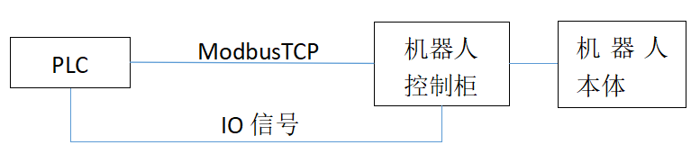 2. Basic Configuration of the Robot2.1 UI Configuration2.1.1 UI Address Allocation
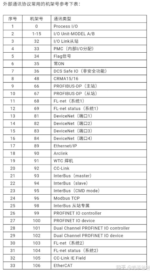
| Range | Rack | Slot | Starting Point | Status |
| UI[1-2] | 48 | 1 | 21 | ACTIVE |
| UI[3-3] | 35 | 1 | 1 | ACTIVE |
| UI[6-6] | 48 | 1 | 23 | ACTIVE |
| UI[8-8] | 35 | 1 | 1 | ACTIVE |
| UI[9-12] | 48 | 1 | 25 | ACTIVE |
2.1.2 UI Definition Allocation
| UI1 | IMSTP |
| UI2 | HOLD |
| UI3 | SFSPD |
| UI6 | START |
| UI8 | ENABLE |
| UI9 | RSR1 |
| UI10 | RSR2 |
| UI11 | RSR3 |
| UI12 | RSR4 |
2.2 UO Configuration2.2.1 UO Address Allocation
| Range | Rack | Slot | Starting Point | Status |
| UO[1-1] | 48 | 1 | 21 | ACTIVE |
| UO[6-6] | 48 | 1 | 22 | ACTIVE |
| UO[9-9] | 48 | 1 | 23 | ACTIVE |
| UO[10-10] | 48 | 1 | 24 | ACTIVE |
2.2.2 UO Definition Allocation
| UO1 | CMD |
| UO6 | FAULT |
| UO9 | BAT |
| UO10 | BUSY |
2.3 Dedicated External Input Set to Enable2.4 Program Selection Method Choose RSR2.5 Set RSR Program Number to 1, Enable3. Robot Modbus TCP Related Configuration3.1 IP Address SettingSet the IP to be on the same subnet as the PLC.3.2 GI Address Allocation
| GI | Rack | Slot | Starting Point | Continuous Bits |
| 1 | 96 | 1 | 1 | 16 |
| 2 | 96 | 1 | 17 | 16 |
| 3 | 96 | 1 | 33 | 16 |
| 4 | 96 | 1 | 49 | 16 |
3.3 GO Address Allocation
| GO | Rack | Slot | Starting Point | Continuous Bits |
| 1 | 96 | 1 | 1 | 16 |
| 2 | 96 | 1 | 17 | 16 |
| 3 | 96 | 1 | 33 | 16 |
| 4 | 96 | 1 | 49 | 16 |
4. PLC Control of the Robot4.1 Select Program 1: Set RSR1 to ON.4.2 Run Robot Program: Set both HOLD and IMSTP to ON; give START a falling edge.4.3 Pause Robot Program: Simply set HOLD to FALSE.4.4 The PLC writes values to GI via Modbus TCP to control the robot’s actions. The robot writes values to GO, and then the PLC reads GO to get feedback.Appendix: