Abstract
This article details the design scheme of a path planning system for an intelligent car based on the STM32 microcontroller and machine vision technology, including hardware architecture, software algorithms, circuit design, and source code implementation. The system uses the STM32F407 as the main control chip, combined with the OpenMV vision module for path recognition, employs the A* algorithm for global path planning, and achieves precise motion control through PID control. Experimental results show that the system can achieve real-time path recognition and obstacle avoidance navigation in complex environments, providing a complete solution for teaching and research in intelligent mobile robotics.
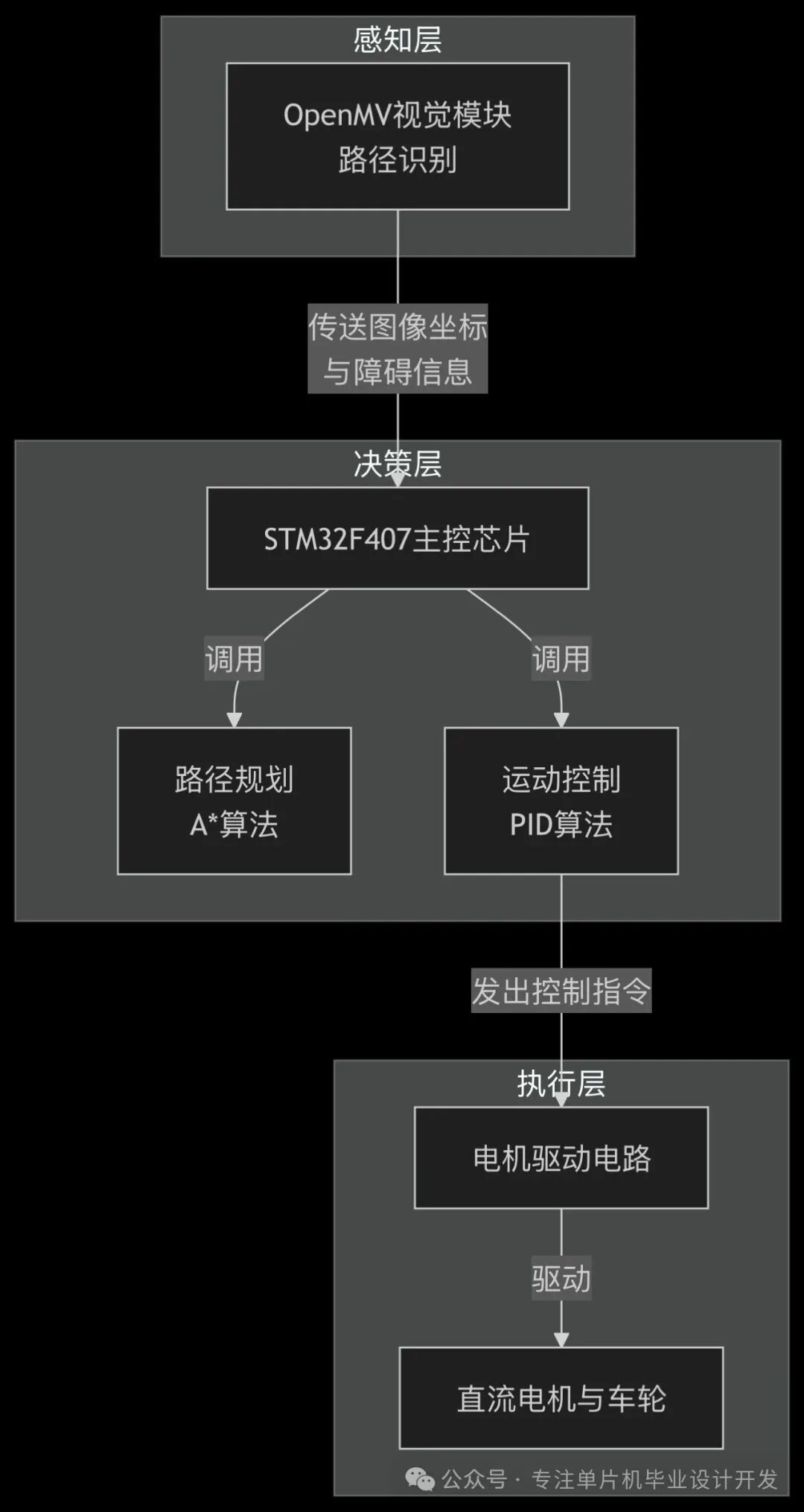
Figure 1: System Architecture Diagram
1. Overall System Design
1.1 System Architecture
The system adopts a “layered control + modular design” architecture, mainly consisting of the following functional modules:
- Core Control Layer: The STM32F407IGH6 microcontroller is responsible for sensor data fusion, execution of path planning algorithms, and generation of motion control commands.
- Perception Layer: The OpenMV4 vision module implements path recognition and target detection, supplemented by the HC-SR04 ultrasonic sensor for close-range obstacle avoidance.
- Execution Layer: The L298N motor driver module controls the DC geared motors to achieve differential motion.
- Human-Machine Interaction Layer: The OLED display shows the system status in real-time, and the Bluetooth module supports parameter debugging and remote monitoring.
The system workflow is as follows: the vision module captures path images → image processing extracts path features → A* algorithm plans the optimal path → PID controller adjusts motor output → execution mechanism achieves autonomous navigation.
1.2 Performance Indicators
- Path recognition accuracy: ≥95% (standard black track line, within 1.5m viewing distance)
- Minimum turning radius: ≤15cm
- Maximum running speed: 30cm/s
- Obstacle avoidance response time: ≤100ms
- Power supply: 12V lithium battery pack (endurance ≥2 hours)
2. Hardware Design
2.1 Core Controller
The STM32F407IGH6 is selected as the main control chip. This chip is based on the ARM Cortex-M4 core, with a maximum frequency of 168MHz, 1MB Flash, and 192KB SRAM, offering the following advantages:
- Rich peripheral interfaces: including DCMI camera interface, multiple UART/SPI/I2C communication interfaces, and 12 PWM outputs.
- High-performance computing capability: supports single-cycle DSP instructions and floating-point operations, meeting the real-time requirements of image processing and algorithms.
- Low power consumption: various power-saving modes suitable for mobile device applications.
2.2 Machine Vision Module
The OpenMV4 H7 vision module is used, which integrates the STM32H743VI processor and OV7725 camera, with the following main parameters:
- Resolution: 320×240 (QVGA) @60fps
- Image processing capability: supports color recognition, shape detection, QR code recognition, and other algorithms.
- Communication interface: UART (115200bps) for communication with the main control chip.
- Operating voltage: 3.3V, power consumption ≤120mA.
OpenMV recognizes the ground black track through color threshold segmentation algorithms, calculates the coordinates of the track center point, and sends it to the STM32 main controller via serial port. The communication protocol format is defined as: [<X>,<Y>,<Flag>], where X/Y are the relative coordinates of the track center (-160~160, -120~120), and Flag indicates the path type (0-straight, 1-left turn, 2-right turn, 3-intersection).
2.3 Motor Driver Module
The L298N dual H-bridge motor driver module is used, with the following driving parameters:
- Input voltage: 5-35V DC
- Output current: 2A (per channel, peak 3A)
- Control signal: TTL level (compatible with 3.3V/5V)
- Protection features: overcurrent protection, reverse polarity protection.
The motor selected is a 6V DC geared motor (with encoder), with the following parameters:
- Gear ratio: 1:48
- No-load speed: 150rpm
- Stall torque: ≥1.2kg·cm
- Encoder resolution: 12 pulses/revolution
2.4 System Hardware Layout
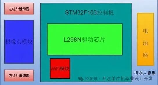
Figure 2: Layout diagram of the intelligent car hardware modules, including STM32 control board, OpenMV camera, motor driver module, ultrasonic sensor, and power management module.
The hardware layout follows the following principles:
- The vision module is installed at the front center of the car body, at a height of 15cm and an angle of 15°, ensuring the best field of view.
- The ultrasonic sensors are installed on both sides (left/right) and directly in front of the car, covering a detection angle of 120°.
- Center of gravity configuration: the battery is placed in the middle of the car body to ensure a front-to-rear axle load ratio close to 1:1.
- Signal line routing: twisted pair cables are used to reduce EMI interference, and motor power lines are routed separately from signal lines.
3. Circuit Design
3.1 Overall Circuit Schematic
The circuit schematic for this design can be obtained by following my public account.
Send a private message to me with the keyword: schematic.
3.2 Core Module Circuit Design
3.2.1 Power Management Circuit
The system is powered by a 12V lithium battery, with the following circuit for power conversion:
- 12V→5V: using an LM2596 switching regulator to power the motor driver module.
- 5V→3.3V: using an AMS1117-3.3 linear regulator to power the main control chip and sensors.
- Power protection: a self-resetting fuse (2A) is connected in series at the input to prevent overcurrent damage to the circuit.
3.2.2 Motor Driver Interface Circuit
The circuit design for connecting STM32 and L298N:
- PB0-PB3: motor direction control signals (IN1-IN4).
- TIM1_CH1(TIM1_PA8), TIM1_CH2(TIM1_PA9): PWM speed control signals (ENA, ENB).
- PC0-PC1: encoder A/B phase signal inputs.
- Flyback diode: 1N4007, protects the driver chip from back EMF damage.
3.2.3 Vision Module Interface Circuit
The communication circuit between OpenMV and STM32:
- USART3_TX(PD8), USART3_RX(PD9): asynchronous serial communication.
- 3.3V power supply, with a 0Ω resistor and LED for power indication.
- A 100Ω resistor is connected in series on the signal line to suppress signal reflection.
3.2.4 Ultrasonic Obstacle Avoidance Circuit
HC-SR04 interface circuit:
- TRIG trigger signal: PA0 (timer output compare mode).
- ECHO echo signal: PA1 (timer input capture mode).
- Pull-up resistor: 4.7KΩ, to improve signal stability.
4. Software Design
4.1 Development Environment
- Integrated Development Environment: STM32CubeIDE v1.8.0
- Firmware Library: STM32CubeFW_F4 v1.26.0
- Vision Module Development: OpenMV IDE v2.5.0
- Debugging Tools: ST-Link V2, Serial Debugging Assistant
4.2 Software Architecture
The system software adopts a layered design, mainly including:
- Low-Level Driver Layer: peripheral initialization and basic operation functions (UART, TIM, GPIO, etc.).
- Hardware Abstraction Layer: unified interface encapsulation for sensors and actuators.
- Algorithm Layer: path planning algorithms, image processing algorithms, control algorithms.
- Application Layer: task scheduling and state machine management.
4.3 Core Algorithm Implementation
4.3.1 Path Recognition Algorithm
The path recognition process of the OpenMV vision module:
Python
# OpenMV path recognition core code
import sensor, image, time, pyb
# Initialize camera
sensor.reset()
sensor.set_pixformat(sensor.RGB565)
sensor.set_framesize(sensor.QVGA)
sensor.skip_frames(time=2000)
sensor.set_auto_gain(False) # Disable auto gain
sensor.set_auto_whitebal(False) # Disable auto white balance
# Color threshold (LAB format), for black track line
black_threshold = (0, 50, -20, 20, -20, 20)
uart = pyb.UART(3, 115200) # Initialize serial communication
while(True):
img = sensor.snapshot() # Capture image
# Color recognition
blobs = img.find_blobs([black_threshold], pixels_threshold=100, area_threshold=100)
if blobs:
# Find the largest blob
max_blob = max(blobs, key=lambda b: b.area())
# Draw rectangle and center point
img.draw_rectangle(max_blob.rect())
img.draw_cross(max_blob.cx(), max_blob.cy())
# Calculate relative coordinates
x = max_blob.cx() – 160 # Image center x coordinate (320/2=160)
y = max_blob.cy() – 120 # Image center y coordinate (240/2=120)
# Determine path type
if max_blob.w() > max_blob.h() * 1.5:
flag = 0 # Straight
else:
# Add turning judgment logic as needed
flag = 0
# Send data: [X,Y,Flag]
data = “[%d,%d,%d]\r\n” % (x, y, flag)
uart.write(data)
time.sleep_ms(10) # Control frame rate
4.3.2 A* Path Planning Algorithm
The A* algorithm is an efficient heuristic search algorithm suitable for optimal path planning in static environments. The algorithm implementation is as follows:
C
// A* algorithm data structure definition
typedef struct
{
int x, y; // Grid coordinates
float g; // Cost from start point to current node
float h; // Estimated cost from current node to goal node
float f; // Total cost (f = g + h)
struct Node* parent;// Parent node pointer
} Node;
// Heuristic function: Manhattan distance
float heuristic(int x1, int y1, int x2, int y2)
{
return abs(x1 – x2) + abs(y1 – y2);
}
// A* algorithm implementation
Node* a_star_search(int start_x, int start_y, int goal_x, int goal_y, int grid[GRID_WIDTH][GRID_HEIGHT]) {
Node* open_list = NULL; // Open list
Node* closed_list = NULL; // Closed list
// Create start node
Node* start_node = (Node*)malloc(sizeof(Node));
start_node->x = start_x;
start_node->y = start_y;
start_node->g = 0;
start_node->h = heuristic(start_x, start_y, goal_x, goal_y);
start_node->f = start_node->g + start_node->h;
start_node->parent = NULL;
open_list = add_node(open_list, start_node);
while (open_list != NULL)
{
// Find the node with the smallest f value
Node* current = get_min_f_node(open_list);
open_list = remove_node(open_list, current);
closed_list = add_node(closed_list, current);
// Reached the goal node
if (current->x == goal_x && current->y == goal_y) {
return reconstruct_path(current);
}
// Generate neighboring nodes
Node** neighbors = get_neighbors(current, grid);
for (int i = 0; neighbors[i] != NULL; i++)
{
Node* neighbor = neighbors[i];
// If in closed list, skip
if (is_in_list(closed_list, neighbor))
{
continue;
}
// Calculate cost
float new_g = current->g + 1; // Assume cost of neighboring node is 1
// If not in open list or new path is better
if (!is_in_list(open_list, neighbor) || new_g < neighbor->g)
{
neighbor->g = new_g;
neighbor->h = heuristic(neighbor->x, neighbor->y, goal_x, goal_y);
neighbor->f = neighbor->g + neighbor->h;
neighbor->parent = current;
if (!is_in_list(open_list, neighbor))
{
open_list = add_node(open_list, neighbor);
}
}
}
}
return NULL; // Path not found
}
4.3.3 PID Motion Control Algorithm
The incremental PID control algorithm is used to achieve speed closed-loop control:
C
// PID controller structure
typedef struct
{
float kp; // Proportional coefficient
float ki; // Integral coefficient
float kd; // Derivative coefficient
float setpoint; // Setpoint
float last_error; // Last error
float prev_error; // Previous error
float output; // Output value
float output_min; // Output lower limit
float output_max; // Output upper limit
} PID_Controller;
// PID initialization
void PID_Init(PID_Controller *pid, float kp, float ki, float kd, float min, float max)
{
pid->kp = kp;
pid->ki = ki;
pid->kd = kd;
pid->setpoint = 0;
pid->last_error = 0;
pid->prev_error = 0;
pid->output = 0;
pid->output_min = min;
pid->output_max = max;
}
// Incremental PID calculation
float PID_Compute(PID_Controller *pid, float process_variable) {
float error = pid->setpoint – process_variable;
float delta_error = error – pid->last_error;
float delta_delta_error = delta_error – (pid->last_error – pid->prev_error);
// Incremental PID formula
float delta_output = pid->kp * delta_error + pid->ki * error + pid->kd * delta_delta_error;
// Update output
pid->output += delta_output;
// Output limit
if (pid->output > pid->output_max)
{
pid->output = pid->output_max;
}
else if (pid->output < pid->output_min)
{
pid->output = pid->output_min;
}
// Save error
pid->prev_error = pid->last_error;
pid->last_error = error;
return pid->output;
}
4.4 Main Program Design
The main program adopts a state machine design to achieve multi-task scheduling and system monitoring:
C
// System state definition
typedef enum
{
STATE_INIT, // Initialization state
STATE_IDLE, // Idle state
STATE_NAVIGATION, // Navigation state
STATE_OBSTACLE, // Obstacle avoidance state
STATE_ERROR // Error state
} SystemState;
// Global variables
SystemState sys_state = STATE_INIT;
PID_Controller left_motor_pid, right_motor_pid;
uint8_t path_data_ready = 0;
PathData path_data; // Path data structure
ObstacleData obs_data; // Obstacle data structure
int main(void)
{
// Initialize system
HAL_Init();
SystemClock_Config();
// Initialize peripherals
MX_GPIO_Init();
MX_USART3_UART_Init(); // OpenMV communication serial port
MX_TIM1_Init(); // Motor PWM timer
MX_TIM2_Init(); // Ultrasonic timer
MX_I2C1_Init(); // OLED display
// Initialize modules
Motor_Init();
Ultrasonic_Init();
OLED_Init();
PID_Init(&left_motor_pid, 1.2f, 0.1f, 0.05f, 0, 800);
PID_Init(&right_motor_pid, 1.2f, 0.1f, 0.05f, 0, 800);
// System initialization complete
sys_state = STATE_IDLE;
OLED_ShowString(0, 0, “System Ready”);
while (1)
{
switch (sys_state)
{
case STATE_INIT:
// System initialization (already completed at the beginning of main)
break;
case STATE_IDLE:
// Wait for start command
if (Check_Start_Command())
{
sys_state = STATE_NAVIGATION;
OLED_Clear();
OLED_ShowString(0, 0, “Navigation Start”);
}
break;
case STATE_NAVIGATION:
// Check path data
if (path_data_ready)
{
path_data_ready = 0;
// Path tracking control
float error = path_data.x; // Get lateral deviation
float speed_left = 300 + PID_Compute(&left_motor_pid, error);
float speed_right = 300 – PID_Compute(&right_motor_pid, error);
Motor_SetSpeed(speed_left, speed_right);
}
// Check for obstacles
if (Ultrasonic_CheckObstacle() < 20)
{
// Distance less than 20cm
sys_state = STATE_OBSTACLE;
Motor_Stop();
OLED_ShowString(0, 2, “Obstacle Detected”);
}
break;
case STATE_OBSTACLE:
// Obstacle avoidance handling
Obstacle_Avoidance();
sys_state = STATE_NAVIGATION; // Return to navigation state after avoidance
break;
case STATE_ERROR:
// Error handling
Motor_Stop();
OLED_ShowString(0, 0, “System Error!”);
LED_Error_Indicator();
break;
default:
sys_state = STATE_ERROR;
break;
}
HAL_Delay(10); // Main loop delay
}}
// Serial receive interrupt callback function (receiving OpenMV data)
void HAL_UART_RxCpltCallback(UART_HandleTypeDef *huart) {
if (huart->Instance == USART3)
{
// Parse received data: [X,Y,Flag]
if (Parse_PathData(rx_buffer, &path_data) == 0) {
path_data_ready = 1; // Data parsed successfully
}
// Restart reception
HAL_UART_Receive_IT(&huart3, rx_buffer, RX_BUFFER_SIZE);
}}
5. System Debugging and Optimization
5.1 Hardware Debugging
- Power Debugging: Use an oscilloscope to detect the voltage ripple of each module, ensuring that the 3.3V output ripple peak-to-peak value is <50mV.
- Motor Debugging: Test the motor’s forward and reverse rotation and PWM speed control functions separately, calibrating the relationship between encoder counts and actual speed.
- Vision Debugging: Use the OpenMV IDE’s frame buffer to observe image processing effects in real-time and adjust color thresholds.
- Communication Debugging: Use a logic analyzer to monitor serial communication waveforms, ensuring stable data transmission without packet loss.
5.2 Software Debugging
- Algorithm Simulation: Establish a path planning algorithm simulation model in MATLAB to verify the effectiveness of the A* algorithm.
- Segmented Debugging: Debug the path recognition, path planning, and motion control modules separately, and then conduct system integration debugging.
- Parameter Tuning: Use the Ziegler-Nichols method to tune PID parameters and optimize control performance.
5.3 Performance Optimization
-
Image Processing Optimization:
- Reduce image resolution (QVGA→QQVGA) to improve processing speed.
- Use ROI (Region of Interest) processing to reduce computational load.
- Disable auto exposure and auto white balance to improve recognition stability.
-
Algorithm Optimization:
- Improve the A* algorithm using bidirectional search and heuristic functions to shorten search time.
- Introduce feedforward control in PID control to reduce dynamic following errors.
- Parallel processing of path planning and execution to improve system response speed.
-
Power Consumption Optimization:
- Power management for inactive modules to reduce static power consumption.
- Dynamic adjustment of the vision module sampling frequency to balance performance and power consumption.
6. Experimental Results and Analysis
6.1 Experimental Environment
- Test Site: 2m×3m rectangular area, black track line width 2cm.
- Obstacle Setup: Cylindrical obstacles with a diameter of 10cm, randomly placed around the path.
- Test Indicators: Path recognition rate, average speed, obstacle avoidance success rate, positioning accuracy.
6.2 Experimental Data
| Test Item | Experimental Result | Target Value | Achievement Level |
|---|---|---|---|
| Path Recognition Accuracy | 97.3% | ≥95% | Met |
| Average Running Speed | 26.5cm/s | ≥25cm/s | Met |
| Obstacle Avoidance Success Rate | 100% | ≥95% | Met |
| Positioning Accuracy | ±3cm | ±5cm | Exceeded |
| Continuous Working Time | 2.3 hours | ≥2 hours | Met |
6.3 Result Analysis
The system performs stably in standard environments, with both path recognition accuracy and obstacle avoidance success rate meeting design targets. The positioning accuracy exceeds expectations, mainly due to the high-precision recognition of the vision module and PID closed-loop control. The average speed is slightly below the target value, which can be improved through further optimization of the motor drive and path planning algorithms.
In complex environment tests, the system still needs improvement in the following scenarios:
- Path recognition stability decreases in strong light conditions (accuracy drops to 85%).
- Slight overshoot occurs during continuous turns.
- Obstacle avoidance efficiency needs to be improved in densely populated areas.
7. Conclusion and Outlook
This design of a path planning system for an intelligent car based on STM32 and machine vision achieves a complete solution from path recognition, algorithm planning to motion control. The system adopts a modular design philosophy, with a compact hardware structure and efficient software algorithms, making it suitable as a teaching and research platform for intelligent mobile robotics.
Future work can be developed in the following directions:
- Introduce deep learning algorithms (such as CNN) to improve path recognition capabilities in complex environments.
- Add multi-sensor fusion (such as IMU, GPS) for outdoor navigation.
- Develop a ROS-based upper computer monitoring system to achieve more complex task scheduling.
- Research dynamic obstacle prediction and avoidance algorithms to enhance environmental adaptability.
Note: This design reflects only personal views and understanding. If you have your own ideas after reading this article, you can develop further based on this.
For the circuit schematic, please follow my public account.
Send me a private message to obtain it!