💥💥💞💞Welcome to this blog❤️❤️💥💥
🏆Author’s Advantage: 🌞🌞🌞The blog content aims to be logically clear and coherent for the convenience of readers.
⛳️Motto: A journey of a hundred miles begins with a single step.
💥1 Overview
The analysis of reinforced concrete member cross-sections focuses on the cross-sectional analysis of members (such as beams and columns) in reinforced concrete structures. The aim is to understand the internal stress conditions, stress distribution, and potential defects or damages within the members. The primary purpose of cross-sectional analysis of reinforced concrete members is to assess the health status of the structure, detect possible defects or damages, and evaluate the load-bearing capacity and safety of the structure. Cross-sectional analysis can also be used to diagnose potential damages or defects in the structure, such as cracks, corrosion, and rusting, allowing for timely repair or reinforcement measures to ensure the safe and reliable operation of the structure. Overall, the analysis of reinforced concrete member cross-sections is an important structural assessment method that provides a comprehensive understanding of the stress conditions and health status of the structure, offering a scientific basis for maintenance, repair, and safe operation.
Abstract
The analysis of reinforced concrete member cross-sections is an important method for assessing structural health, detecting defects and damages, and evaluating load-bearing capacity. Through cross-sectional analysis, one can gain a comprehensive understanding of the internal stress conditions and stress distribution of members, timely identifying defects such as cracks and corrosion, thus providing a scientific basis for structural maintenance, repair, and safe operation.
Keywords
Reinforced concrete members; Cross-sectional analysis; Structural health; Defect detection; Load-bearing capacity
1 Introduction
Reinforced concrete structures are widely used in fields such as buildings, bridges, and tunnels, and the load-bearing performance and health status of their members (such as beams and columns) directly affect the overall structural safety. Cross-sectional analysis, as a key means of structural assessment, can reveal the internal stress distribution, defect locations, and severity of members, providing data support for structural reinforcement and repair.
2 Overview of Cross-Sectional Analysis of Reinforced Concrete Members
2.1 Definition and Purpose
Cross-sectional analysis of reinforced concrete members refers to the method of cutting sections perpendicular to the axis of the members, assessing the health status of the structure by observing the cross-sectional shape, material properties, and stress distribution. Its core purposes include:
Structural health assessment: Quantifying the load-bearing capacity and safety of members.
Defect detection: Identifying damages such as cracks, corrosion, and rusting.
Maintenance decision support: Providing scientific basis for repair and reinforcement.
2.2 Importance
Cross-sectional analysis is a core aspect of the entire lifecycle management of structures:
Preventive maintenance: Early defect detection to avoid catastrophic failures.
Optimized design: Feedback on material performance and stress data to improve structural design.
Cost control: Reducing unplanned maintenance and extending the service life of structures.
3 Methods and Techniques for Cross-Sectional Analysis
3.1 Traditional Methods
3.1.1 Experimental Methods
Material property testing: Obtaining parameters such as elastic modulus and yield strength of concrete and steel through compression and tensile tests.
Cross-sectional property measurement: Calculating geometric parameters such as cross-sectional area, moment of inertia, and section modulus.
3.1.2 Theoretical Calculations
Plane section assumption: Assuming that the deformed cross-section remains planar, with strain distributed linearly along the height.
Layered method: Dividing the cross-section into thin layers to analyze the stress-strain relationship of each layer.
3.2 Modern Technologies
3.2.1 Finite Element Analysis (FEA)
Modeling and simulation: Using software (such as ANSYS, ABAQUS) to establish a three-dimensional model of the member and simulate complex loading conditions.
Nonlinear analysis: Considering material plasticity, crack propagation, and other nonlinear behaviors to improve analysis accuracy.
3.2.2 MATLAB Programming
Cross-sectional property calculation: Automating the calculation of parameters such as cross-sectional area and moment of inertia through scripts.
b = 0.3; % Width (m)
h = 0.5; % Height (m)
A = b * h; % Cross-sectional area
I = (b * h^3) / 12; % Moment of inertia
yc = h / 2; % Distance to neutral axis
S = I / yc; % Section modulus
fprintf('Cross-sectional area: %.2f m²\n', A);
fprintf('Moment of inertia: %.2f m⁴\n', I);
Material property integration: Combining the constitutive models of concrete and steel to simulate the stress behavior of the cross-section.
3.2.3 Non-Destructive Testing Techniques
Ultrasonic testing: Evaluating internal defects through sound wave propagation speed and attenuation.
Radar scanning: Using electromagnetic wave reflection imaging to identify the position of steel bars and corrosion conditions.
4 Cross-Sectional Analysis Process
4.1 Preliminary Preparation
Data collection: Obtaining design drawings, material property parameters, and historical inspection records of the members.
Tool preparation: Selecting cutting equipment, strain gauges, displacement sensors, etc.
4.2 Section Cutting and Observation
Cutting position selection: Determining based on stress concentration areas or historical damage records.
Cross-section protection: Preventing secondary damage to materials during the cutting process.
4.3 Stress Analysis and Stress Calculation
Internal force determination: Calculating the bending moment, shear force, etc., of the cross-section based on structural stress analysis results.
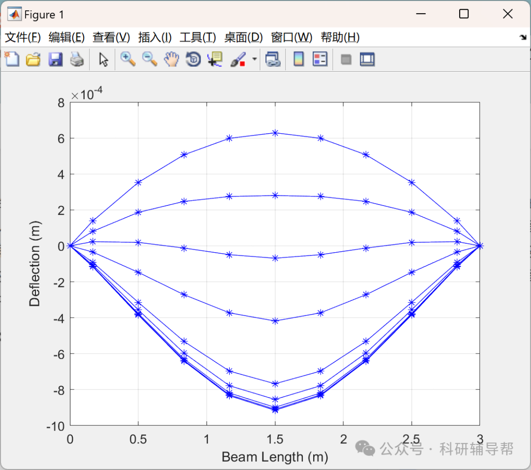
Stress distribution simulation: Using the plane section assumption or finite element model to draw stress contour maps of the cross-section.
4.4 Load-Bearing Capacity Assessment and Optimization
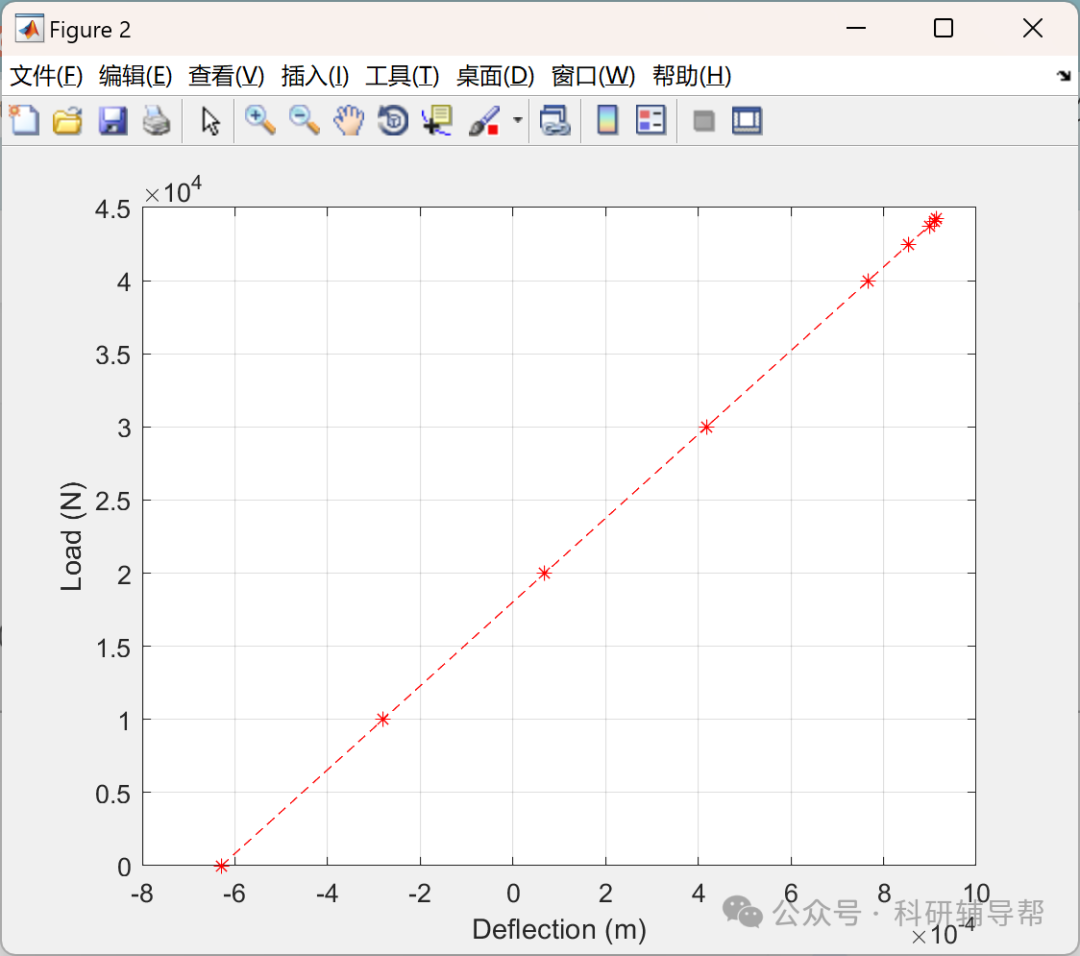
Load-bearing capacity calculation: Comparing the actual stress of the cross-section with the design strength of the material to assess safety reserves.
Optimized design: Adjusting the configuration of steel bars or cross-sectional dimensions based on analysis results.
5 Case Analysis
5.1 Case 1: Cross-Sectional Analysis of a Bridge Beam
Problem description: Cracks appeared in a certain bridge beam, requiring load-bearing capacity assessment.
Analysis process:
Cutting the beam cross-section to observe crack distribution and steel bar corrosion conditions.
Calculating the moment of inertia and bending modulus of the cross-section using MATLAB.
Using a finite element model to simulate stress distribution under vehicle loads.
Result: It was found that the cracks were caused by steel bar corrosion, leading to a 20% reduction in load-bearing capacity, requiring reinforcement.
5.2 Case 2: Cross-Sectional Analysis of a Building Column
Problem description: The axial compression ratio of a high-rise building column exceeded the limit, requiring safety verification.
Analysis process:
Cutting the column cross-section to measure the depth of concrete carbonation and the diameter of the steel bars.
Calculating the compressive load-bearing capacity of the cross-section using the layered method.
Assessing compliance with axial compression ratio requirements based on code requirements.
Result: The load-bearing capacity of the column met the requirements, but structural measures needed to be strengthened.
6 Conclusion and Outlook
6.1 Conclusion
The analysis of reinforced concrete member cross-sections is a core method for structural safety assessment. By combining traditional experiments with modern technologies, precise defect detection and quantitative load-bearing capacity assessment can be achieved. The application of MATLAB programming and finite element analysis significantly enhances analysis efficiency and accuracy.
6.2 Outlook
Future research may focus on:
Integration of intelligent algorithms: Combining machine learning to optimize defect identification models.
Multi-scale analysis: Achieving cross-scale simulation from material microstructure to macro performance of components.
Real-time monitoring technology: Developing embedded sensors to achieve dynamic tracking of structural health status.
📚2 Running Results


Main function code:
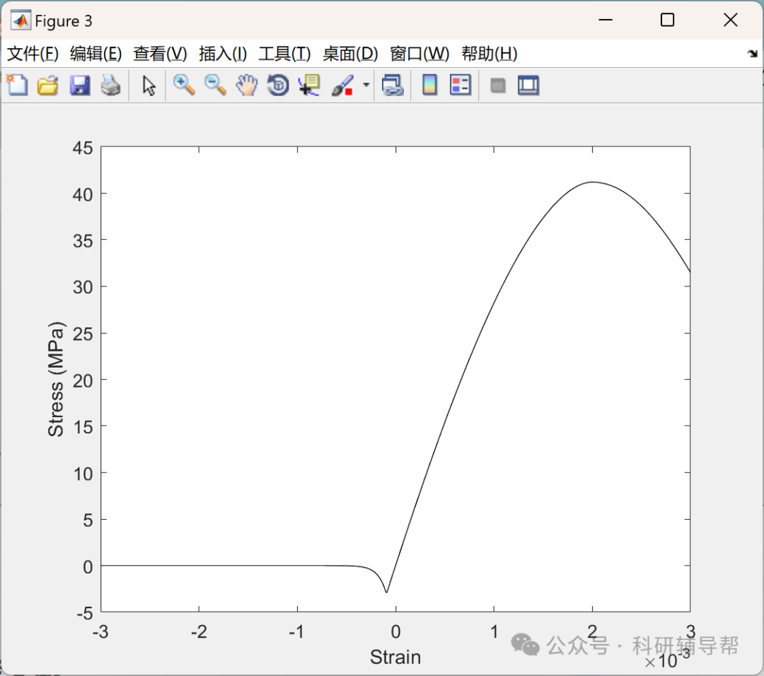
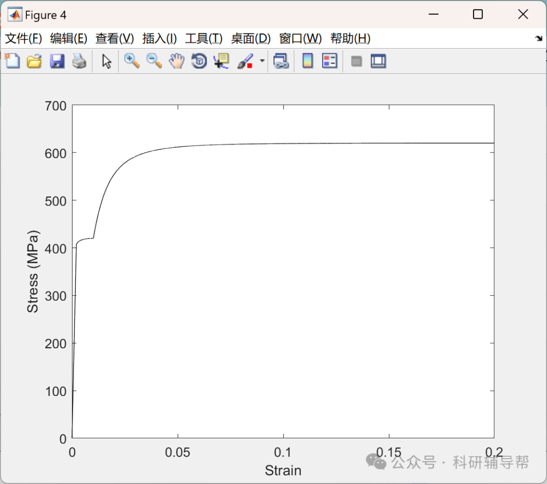
clear; clc; close all;%Input%————————————————————————–Materials.concrete=[41.2*10^6 3.05*10^6 0.002 250 32.5*10^9 0.003];Materials.steel=[0.008 0.99 420*10^6 620*10^6 0.2 200*10^9 0 ; 0 0.99 1437.85*10^6 1846.55*10^6 0.06 165.35*10^9 623/165350 ; 0 0.99 1437.85*10^6 1846.55*10^6 0.06 165.35*10^9 1027.4/165350 ; 0 0.99 1437.85*10^6 1846.55*10^6 0.06 165.35*10^9 0];Materials.fiber=[200*10^9 0.001];Section.figure{1}.concrete_type=1;Section.figure{1}.No_steel_bars=7;Section.figure{1}.steel_bars_properties=[ 1 0.785*10^-4 -0.076 0.114 ; 1 0.785*10^-4 0.076 0.114 ; 2 0.96535*10^-4 0 0.114 ; 3 0.96535*10^-4 -0.076 -0.081 ; 3 0.96535*10^-4 0.076 -0.081 ; 4 0.96535*10^-4 -0.076 -0.121 ; 4 0.96535*10^-4 0.076 -0.121];Section.figure{1}.No_fiber_bars=0;Section.figure{1}.fiber_bars_properties=[1 0 0 0];Section.figure{1}.vertices.x=[-0.106 0.106 0.106 -0.106];Section.figure{1}.vertices.y=[-0.151 -0.151 0.151 0.151];Section.figure{1}.NX=2;Section.figure{1}.NY=50;Beam.Portion{1}.Section=Section;Beam.Portion{1}.NL=9;Beam.Portion{1}.L_min=0;Beam.Portion{1}.L_max=3;

🎉3 References
Some content in this article is sourced from the internet, and references will be noted. If there are any inaccuracies, please feel free to contact us for removal.
[1] Sohaib M, Hasan J M, Chen J, et al. Generalizing infrastructure inspection: step transfer learning aided extreme learning machine for automated crack detection in concrete structures[J]. Measurement Science and Technology, 2024, 35(5).
[2] Hang X, Zhu X, Gao X, et al. Study on crack monitoring method of wind turbine blade based on AI model: Integration of classification, detection, segmentation and fault level evaluation[J]. Renewable Energy, 2024, 224.
🌈4 MATLAB Code Implementation
Reply in the public account: Program download