🔌 How Many Pins Does STM32 Have? Why Can One Pin Serve Multiple Functions?
Almost all beginners with STM32 will be confused:
👉 How many pins does STM32 actually have?👉 Are pin 0 of GPIOA and pin 0 of GPIOB duplicated?👉 Why can one pin have multiple functions without conflict?
Let’s clarify this systematically and engineering-wise.
🧩 1. STM32 Pin Count ≠ Function Count
The “pin count” of STM32 chips refers to the number of physical pins (e.g., 48-pin, 64-pin, 100-pin packages); while the “pin functions” refer to the logical functions (GPIO, UART, I2C, ADC, TIM, SPI, etc.).
For example:
-
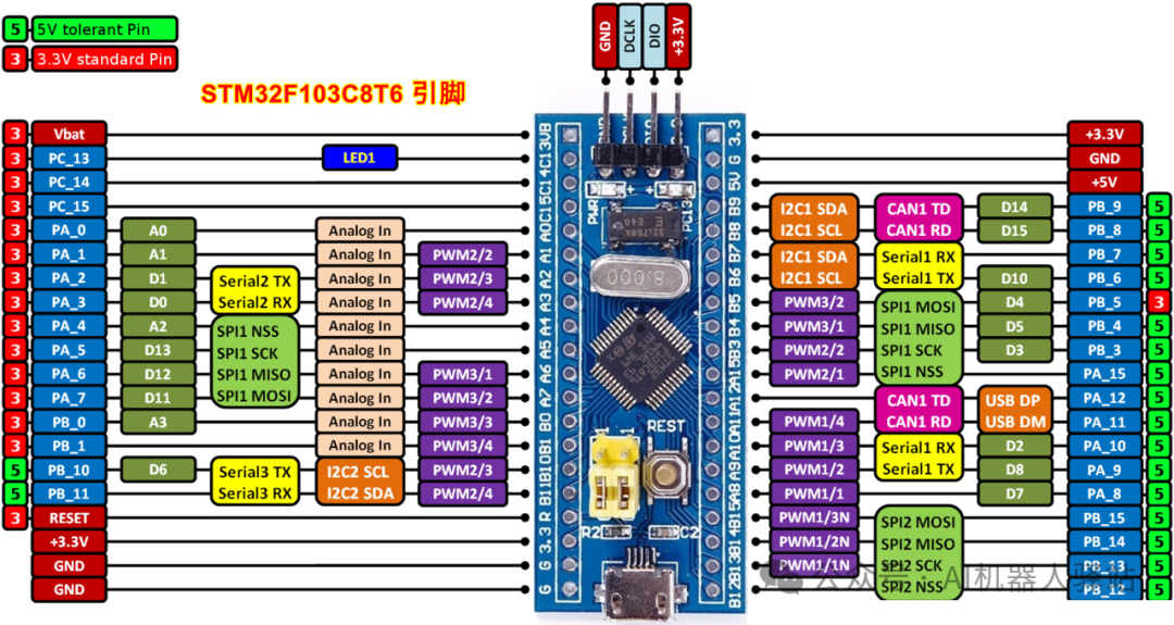
STM32F103C8T6 is a 48-pin package;
-
Approximately 37 GPIOs are actually available;
-
However, each pin can have multiple multiplexed functions, so the total “function count” > physical pin count.
🧮 2. Naming Convention: Port + Pin Number
The GPIO naming of STM32 follows a unified rule:
| Name Part | Meaning |
|---|---|
| Port Number | Indicates the GPIO group (e.g., GPIOA, GPIOB, GPIOC, etc.) |
| Pin Number | Indicates the pin number within that port (0–15) |
📘 Each port can have a maximum of 16 pins (0~15), but not all chip models expose all pins.
For example:
-
STM32F103C8T6: has GPIOA~GPIOC, totaling 3×16=48 pins, but some are not packaged;
-
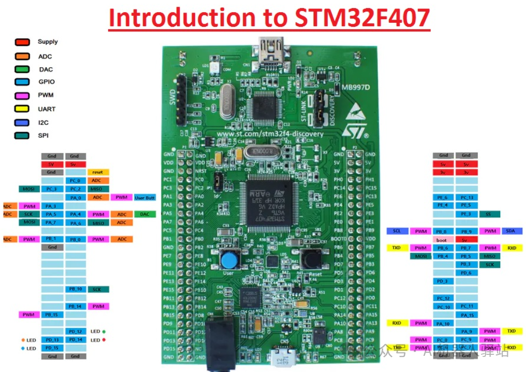
STM32F407: has GPIOA~GPIOI, with up to 144 pin packages.
👉 Even if pin 0 of GPIOA and pin 0 of GPIOB have the same number, they are still different physical pins, controlled by different port registers, and do not interfere with each other.
⚙️ 3. Multifunctional Design of Each Pin (Multiplexing)
STM32 pins typically have up to 3~5 functions, achieved through the Alternate Function (AF) mechanism.
🔹 For example:
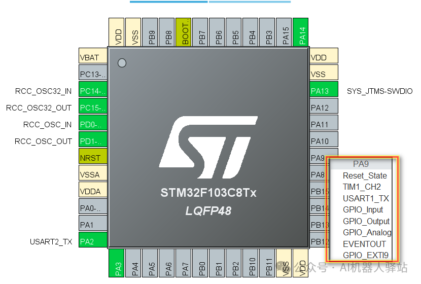
Pin 9 of GPIOA can be configured as:
-
Standard GPIO output;
-
USART1_TX serial port;
-
TIM1_CH2 timer;
-
I2C_SCL (for some models).
These are determined by setting the Alternate Function Register (AFR) for the pin.
Example code:
GPIO_InitStruct.Pin = GPIO_PIN_9;
GPIO_InitStruct.Mode = GPIO_MODE_AF_PP;  // Multiplexed push-pull output
GPIO_InitStruct.Alternate = GPIO_AF7_USART1; // Specify alternate function
HAL_GPIO_Init(GPIOA, &GPIO_InitStruct);
✅ Reasons for No Conflicts:
A pin can only operate in one mode at any given time;
Even if it supports multiple functions, only the one selected through the register is active;
Other functions are logically “disconnected”.
🔩 4. Real Examples of Multiplexing Conflicts
If two peripherals multiplex the same pin:
-
For example, both USART1_TX and TIM1_CH2 require GPIOA Pin 9;
-
You can only choose one peripheral to use;
-
The other cannot be enabled (CubeMX will indicate a conflict).
🧠 Engineering Approach:
-
Open CubeMX;
-
Select the peripheral you want to enable;
-
CubeMX automatically assigns available pins;
-
If there is a conflict, it will show a red warning, prompting you to change the pin.
🧰 5. Calculation of Unique Pin Index
From a software perspective,<span>GPIO(port) + Pin(number)</span> combination is already a unique index.
You can map the “port number” to a numeric identifier and calculate the unique index:
| Port | Numeric Identifier | Index Formula |
|---|---|---|
| GPIOA | 0 | (0 × 16 + PinNum) |
| GPIOB | 1 | (1 × 16 + PinNum) |
| GPIOC | 2 | (2 × 16 + PinNum) |
| GPIOD | 3 | (3 × 16 + PinNum) |
| GPIOE | 4 | (4 × 16 + PinNum) |
For example:
GPIOA Pin 3 → index = 3
GPIOB Pin 0 → index = 16
GPIOC Pin 15 → index = 47
This way, software can manage all pins with a unified identifier.
🧭 6. Naming Design Logic
The pin naming system of STM32 reflects four design concepts:
| Design Goal | Description |
|---|---|
| Unified Architecture | All Cortex-M series GPIO modules support a 16-bit port structure |
| Modular Packaging | Different package models can trim the number of ports to match the package size |
| Flexible Multiplexing | The number of peripherals exceeds the number of pins, achieving maximum compatibility through the AF mechanism |
| Hardware Isolation | Only one function is valid at any time, avoiding electrical conflicts |
🔎 7. Quick Summary
| Concept | Meaning |
|---|---|
| Physical Pin | The actual metal pins on the package |
| GPIO Port | GPIOA~GPIOE, with a maximum of 16 pins per group |
| Logical Number | GPIOx Pin_y, used for software access |
| Multiplexing Function | The same pin can be shared by multiple peripherals, selected via registers |
| Conflict Mechanism | A pin cannot be used by multiple functions simultaneously |
| Unique Index | Port number × 16 + Pin number, ensuring global uniqueness |
🌟 8. Example (STM32F103C8T6)
| Pin | Function 1 | Function 2 | Function 3 |
|---|---|---|---|
| GPIOA Pin 9 | GPIO | USART1_TX | TIM1_CH2 |
| GPIOA Pin 10 | GPIO | USART1_RX | TIM1_CH3 |
| GPIOB Pin 6 | GPIO | I2C1_SCL | TIM4_CH1 |
| GPIOB Pin 7 | GPIO | I2C1_SDA | TIM4_CH2 |
In practical engineering:
-
If using serial port 1, configure pins 9 and 10 of GPIOA;
-
If using I2C1, configure pins 6 and 7 of GPIOB;
-
Both cannot be multiplexed simultaneously.
📘 9. Mnemonic
“Each pin can have many names, but at any one time, it can only wear one outfit.”