Click 👆 aboveFollowEngineer Yan Ji and ★ Star Mark ★.
Modbus-RTU Protocol
The RTU ADU is shown in the figure below.

In addition to the core PDU, this ADU contains only two pieces of information. First, the address is used to define the slave device corresponding to the PDU. In most networks, address 0 is defined as the “broadcast” address. This means that the master device can send output commands to address 0, and all slave devices should process this request but not respond. Besides this address, the CRC is also used to ensure data integrity.
The pair of silent times at the beginning and end of the data packet requires that the message transmission starts with a pause of at least 3.5 byte times, which is a period during which there is no communication on the bus. For a baud rate of 9,600, this rate is approximately 4ms. The standard defines a minimum silence length that is less than 2 ms, regardless of the baud rate. After the last transmitted byte, a pause of at least 3.5 byte times marks the end of the message.
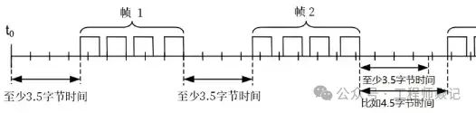
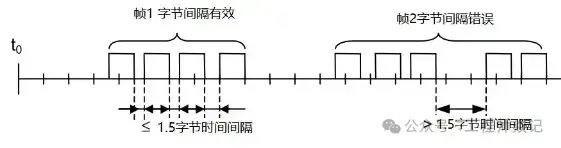
It is also specified that messages must be sent continuously, and the interval between bytes must not exceed 1.5 byte times.
This presents performance drawbacks because devices must wait for the idle time to end before processing the data packet. However, more dangerously, serial transmission introduces different technologies, and the baud rate can be faster than the standard. For example, using a USB/serial converter cable, you cannot control the data packets and data transmission. Tests have shown that using a USB-to-serial cable with the NI-VISA driver introduces variable-sized gaps in the data stream, and these gaps – silent periods – can “fool” compliant code into believing the message is complete. Due to the incomplete message, this often results in an invalid CRC, causing the device to interpret the ADU as corrupted.
Frame structure = Address + Function Code + Data + Checksum
Address: Occupies one byte, ranging from 0-255, where the valid range is 1-247; others have special purposes, such as 0 being the broadcast address (the broadcast address responds to all addresses, and normally requires two devices to have the same address to query and reply). Function Code: Occupies one byte, the meaning of the function code is to know what this instruction is for, for example, you can query data from the slave or modify data, so different function codes correspond to different functions. Data: Varies in structure depending on the function code, as explained in the examples below. Checksum: To ensure data correctness, this is added, and then the previous data is calculated to see if the data is consistent; if consistent, it indicates that this frame of data is correct, and I will reply; if not, it indicates that there was a problem during data transmission, and the data is incorrect, so it is discarded.
Start Bit Device Address Function Code Data CRC Check End Bit
T1-T2-T3-T4 8Bit 8Bit n 8Bit 16Bit T1-T2-T3-T4
| Address Code | Function Code | Data Area | CRC Check |
| 1 Byte | 1 Byte | N Bytes | 2 Bytes |
| Address Code: 1 byte slave address code, =0: broadcast address, =1-247: slave address, =248-255: reserved | Function Code: Commonly used are 01, 02, 03, 04, 05, 06, 15, 16, specific descriptions are shown in the figure below | Data Area: The data area includes several parts: starting address, quantity, data, these three items are in big-endian format | CRC Check: Two bytes, little-endian format, the range of data for the check is: address code + function code + data area |
The most commonly used function codes in the Modbus-RTU protocol are 03 and 06, with most using Modbus to query information on sensors using function code 03; if you need to modify the value of a sensor register, use function code 06.
Send: Slave address + function code + address of the register to be queried + number of registers to be queried + checksum Reply: Slave address + function code sent by the master + number of bytes of data to be sent to the master + data + checksum
Now I am the master, and I want to query the data of the slave address 01, using query function code 0x03
- • Master sends: 01 03 00 00 00 01 84 0A
- • Slave replies: 01 03 02 19 98 B2 7E
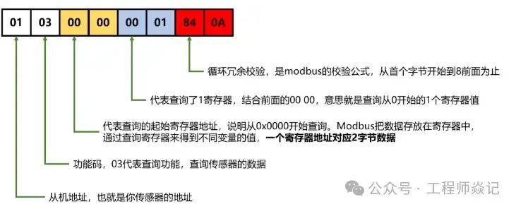
01 – Address, which is the address of your sensor 03 – Function code, 03 represents the query function, querying the data of the sensor 00 00 – Represents the starting register address for the query, indicating that the query starts from 0x0000. It should be noted that Modbus stores data in registers, and different variable values are obtained by querying registers, with one register address corresponding to 2 bytes of data 00 01 – Represents querying one register. Combined with the previous 00 00, it means querying the value of one register starting from 0 84 0A – Cyclic Redundancy Check, which is the Modbus checksum formula, from the first byte to the byte before 84;
Response Data Analysis
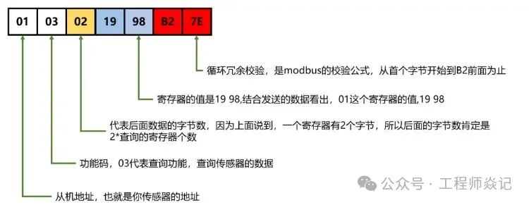
01 – Address, which is the address of your sensor 03 – Function code, 03 represents the query function, querying the data of the sensor. It should be noted that the function code sent to the slave must be the same, and the slave must reply with the same function code; if they are different, it indicates that this frame of data has an error 02 – Represents the number of bytes of the following data, as mentioned above, one register has 2 bytes, so the number of bytes must be 2 * the number of queried registers; 19 98 – The value of the register is 19 98, combined with the sent data shows that the value of register 01 is 19 98 B2 7E – Cyclic Redundancy Check
Function Code 01: Read Coil Status
Example 1: Read the status of 1 coil, coil address is 0:
Master sends: 01 01 00 00 00 01 FD CASlave returns: 01 01 01 00 51 88
Analysis of the data sent by the master:
| 01 | 01 | 00 00 | 00 01 | FD CA |
| Slave Address | Function Code | Starting Address of Coil to Read (Big-endian) | Number of Coils to Read (Big-endian) | CRC Check Code (Little-endian) |
Analysis of the data returned by the slave, only discussing the data area:
- • 01: Number of bytes following
- • 00: Coil status
Example 2: Read the status of 10 coils starting from coil 0:
Master sends: 01 01 00 00 00 0A BC 0DSlave returns: 01 01 02 00 00 b9 fc
Analysis of the data returned by the slave, only discussing the data area:
- • 02: Number of bytes following
- • 00 00: One bit represents the status of one coil
Function Code 02: Read Discrete Input
Protocol format is the same as Function Code 01.
Function Code 03: Read Holding Register
Example 1: Read 1 holding register, holding register address is 0:
Master sends: 01 03 00 00 00 01 84 0ASlave receives: 01 03 02 00 00 b8 44
Analysis of the data sent by the master:
| 01 | 03 | 00 00 | 00 01 | 84 0A |
| Slave Address | Function Code | Starting Address of Holding Register to Read (Big-endian) | Number of Holding Registers to Read (Big-endian) | CRC Check Code (Little-endian) |
Analysis of the data returned by the master, only discussing the data area:
- • 02: Number of bytes following
- • 00 00: Value read from the holding register, big-endian
Example 2: Read 10 holding registers, starting address of holding registers is 0:
Master sends: 01 03 00 00 00 0A C5 CDSlave returns: 01 03 14 00 00 00 00 00 00 00 00 00 00 00 00 00 00 00 00 00 00 00 00 a3 67
Analysis of the data returned by the slave (only discussing the data area):
- • 14: Number of bytes following
- • 00 00 00 00 00 00 00 00 00 00 00 00 00 00 00 00 00 00 00 00: Value read from the holding registers, big-endian, with each register value represented by 2 bytes.
Function Code 04: Read Input Register
Protocol format is the same as Function Code 03.
Function Code 05: Write Single Coil
Example 1: Write coil 0 to 0:
Master sends: 01 05 00 00 00 00 CD CASlave returns: 01 05 00 00 00 00 cd ca
Analysis of the data sent by the master:
| 01 | 05 | 00 00 | 00 00 | CD CA |
| Slave Address | Function Code | Coil Address to Write (Big-endian) | Coil Status to Write (Big-endian) | CRC Check Code (Little-endian) |
The slave returns exactly what the master sends.
Example 2: Write coil 0 to 1:
Master sends: 01 05 00 00 FF 00 8C 3ASlave returns: 01 05 00 00 ff 00 8c 3a
Analysis of the data sent by the master, only discussing the data area:
- • 00 00: Coil address to write, big-endian
- • FF 00: Coil status to write, FF 00 indicates setting the coil to 1
Function Code 06: Write Single Register
Example 1: Write register 0 to 0:
Master sends: 01 06 00 00 00 00 89 CASlave returns: 01 06 00 00 00 00 89 CA
Analysis of the data sent by the master:
| 01 | 06 | 00 00 | 00 00 | 89 CA |
| Slave Address | Function Code | Register Address to Write (Big-endian) | Register to Write (Big-endian) | CRC Check Code (Little-endian) |
The slave returns exactly what the master sends.
Example 2: Write register 0 to 1:
Master sends: 01 06 00 00 00 01 48 0ASlave returns: 01 06 00 00 00 01 48 0a
Function Code 15: Write Multiple Coils
Write 10 coils starting from coil number 0: coils 0-3 write 1, coils 4-7 write 0, coils 8-9 write 1 (0F 03):Master sends: 01 0F 00 00 00 0A 02 0F 03 A0 C9Slave returns: 01 0f 00 00 00 0a d5 cc
Analysis of the data sent by the master:
| 01 | 0F | 00 00 | 00 0A | 02 | 0F 03 | A0 C9 |
| Slave Address | Function Code | Starting Address of Coils to Write (Big-endian) | Number of Coils to Write (Big-endian) | Number of Bytes Following | Coil Status to Write, little-endian, converted to bits from low to high is: 1111 0000 11XX XXXX, X indicates unused, one bit represents the status of one coil | CRC Check Code (Little-endian) |
Analysis of the data returned by the slave, only discussing the data area:
- • 00 00: Starting address of coils written, big-endian
- • 00 0A: Number of coils written, big-endian
Function Code 16: Write Multiple Registers
Write 10 registers starting from register number 0: registers 0-3 write 1, registers 4-7 write 0, registers 8-9 write 1:Master sends: 01 10 00 00 00 0A 14 00 01 00 01 00 01 00 01 00 00 00 00 00 00 00 00 00 01 00 01 4F 13Slave returns: 01 10 00 00 00 0a 40 0e
Analysis of the data sent by the master:
| 01 | 10 | 00 00 | 00 0A | 14 | 00 01 00 01 00 01 00 01 00 00 00 00 00 00 00 00 00 01 00 01 | 4F 13 |
| Slave Address | Function Code | Starting Address of Registers to Write (Big-endian) | Number of Registers to Write (Big-endian) | Number of Bytes Following | Register Values to Write, big-endian, two bytes represent one register value | CRC Check Code (Little-endian) |
Analysis of the data returned by the slave, only discussing the data area:
- • 00 00: Starting address of registers written, big-endian
- • 00 0A: Number of registers written, big-endian
If this article is helpful to you, please follow for more exciting content!Disclaimer: The articles pushed are for readers’ learning and communication purposes only. The copyright of the articles, images, etc. belongs to the original authors, and original works are for reference only. Plagiarists will be pursued, and if there is any infringement, please contact for deletion.If you like the article, give it a “like” or “share” and let’s progress together!