This article introduces the C language and assembly language, which are closer to the hardware level, and explains how the CPU executes code.
High-Level vs Low-Level Languages
Learning to program is essentially learning a language to communicate with computers. Since computers do not understand human languages, a compiler translates the code written by humans into binary code, which can then be executed on machines. Mastering a high-level language does not equate to understanding the actual execution steps of a computer; one must also have some knowledge of C and even assembly language. Programming languages range from low-level to high-level, as shown in the diagram below. Among them, Assembly Language, or assembly, lies between machine language and high-level languages.
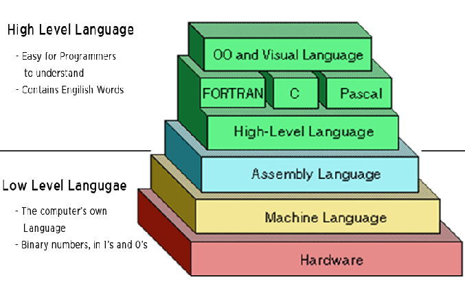
However, computers can only understand low-level languages, which are specifically designed to control hardware.
Assembly language is a type of low-level language that directly describes or controls the operation of the CPU. By learning assembly language, one can understand what the CPU actually does. Related articles recommended: How does the CPU recognize the code we write?
Assembly language is not easy to learn, and most embedded development can be effectively accomplished using C language. Developing in C is more efficient, and the program’s execution efficiency does not significantly decrease. So why learn assembly? Perhaps it is just to get closer to the truth!
How Assembly Language Came About
The CPU, as the core of intelligent devices, is responsible only for computation and does not possess intelligence; it merely executes actions as instructed.
These instructions are in binary, known as opcodes; for example, the addition instruction is represented as 00000011. The role of the compiler is to translate the programs written in high-level languages into a series of opcodes.
In the early days, programming involved manually writing binary instructions, with programs consisting of a string of 0s and 1s. It is said that only a few geniuses could accomplish this in the last century. After writing a series of 01 programs, various switches were used to input them into the computer; for instance, to perform addition, one would press the addition switch. Related articles: Can a CPU be made with a bunch of switches? Later, the invention of the paper tape punch allowed binary instructions to be automatically input into the computer by punching holes in the tape. The following image may represent a segment of computer instructions.

However, this binary programming, which is quite inhuman, is difficult to understand and has poor readability; having someone else maintain it is essentially like starting from scratch! It is impossible to see what the machine has done. To address the readability issue and occasional editing needs, assembly language was born.
In the early days, to solve the readability problem of binary instructions, engineers wrote those binary instructions in octal, but octal also proved to be unreadable. Naturally, the final solution was to express them in text. Assembly language is the textual form of binary instructions, with a one-to-one correspondence with the instructions. For example, the addition instruction 00000011 is written in assembly language as ADD. Memory addresses are no longer referenced directly but are represented using labels.
The process of translating these textual instructions into binary is called assembling, and the program that completes this process is called an assembler. The standardized text it processes is referred to as Assembly Language, abbreviated as asm, with the file extension s.
Registers and Memory Models
Registers
Each CPU’s machine instructions are different, and thus the corresponding assembly language also varies. This article introduces the most common x86 assembly language used by Intel CPUs.
To learn assembly language, one must be familiar with two concepts: registers and memory models. Let’s start with registers.
The CPU itself is responsible only for computation and does not store data. Data is generally stored in memory, and the CPU reads and writes data from memory when needed. However, the CPU’s computation speed is much faster than the read and write speed of memory. To avoid being slowed down, the CPU comes with Level 1 and Level 2 caches. Essentially, the CPU cache can be viewed as a faster memory for reading and writing.
Since the CPU cache is still not fast enough, and the addresses of data in the cache are not fixed, the CPU must address each read and write, which can also slow down speed. Therefore, in addition to the cache, the CPU also has registers to store the most frequently used data. This means that data such as loop variables, which are read and written most frequently, will be placed in registers. The CPU prioritizes reading and writing from registers, and then exchanges data with memory. As shown in the diagram below, the speed is ordered from top to bottom, decreasing.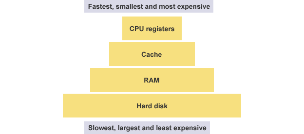
Registers do not distinguish data by address but by name. Each register has its own name, and we tell the CPU which specific register to retrieve data from, making this the fastest method. Some compare registers to the CPU’s zero-level cache.
Early x86 CPUs had only 8 registers, each with different purposes. Modern registers have over 100, and they have become general-purpose registers without specific designations, but the names of the early registers have been preserved.
EAX EBX ECX EDX EDI EBP ESPAmong these 8 registers, the first seven are general-purpose. The ESP register has a specific purpose, storing the address of the current stack.
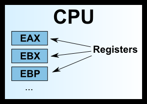
The names we often see, such as 32-bit CPU and 64-bit CPU, actually refer to the size of the registers. A 32-bit CPU has a register size of 4 bytes.
Memory Model: Heap
Registers can only hold a small amount of data; most of the time, the CPU needs to instruct registers to directly exchange data with memory. Therefore, in addition to registers, it is essential to understand how memory stores data. When a program runs, the operating system allocates a segment of memory to it for storing the program and the data generated during execution. This segment of memory has a starting address and an ending address, for example, from 0x1000 to 0x8000, where the starting address is the smaller one and the ending address is the larger one.
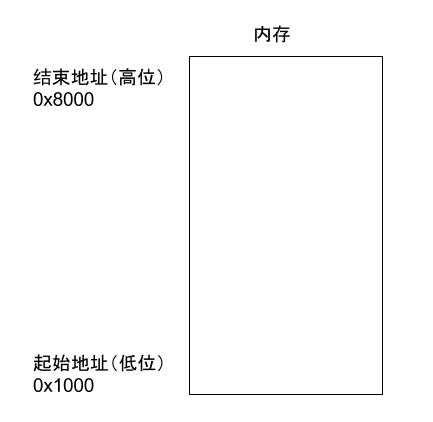
During program execution, for dynamic memory allocation requests (such as creating new objects or using the malloc command), the system will allocate a portion of the pre-allocated memory to the user, with the specific rule being to allocate from the starting address (in reality, the starting address will have a segment of static data, which we will ignore here). For example, if the user requests 10 bytes of memory, it will be allocated starting from the address 0x1000, extending to address 0x100A. If another request for 22 bytes is made, it will be allocated up to 0x1020.
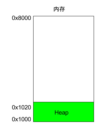
This memory area allocated due to user requests is called the Heap. It grows from the starting address towards higher addresses. An important characteristic of the Heap is that it does not disappear automatically; it must be manually released or reclaimed by a garbage collection mechanism.
Memory Model: Stack
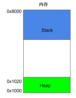
Besides the Heap, other memory usage is referred to as the Stack. In simple terms, the Stack is the memory area temporarily occupied due to function execution.
Consider the following example.
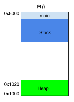
int main() { int a = 2; int b = 3;}In the above code, when the system starts executing the main function, it will create a frame in memory for it, where all internal variables of main (such as a and b) are stored. After the main function finishes executing, that frame will be reclaimed, releasing all internal variables and no longer occupying space.
What happens if a function calls another function?
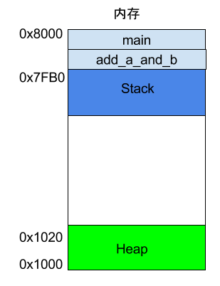
int main() { int a = 2; int b = 3; return add_a_and_b(a, b);}In the above code, the main function calls the add_a_and_b function. When executing this line, the system will also create a new frame for add_a_and_b to store its internal variables. This means that at this point, there are two frames: main and add_a_and_b. Generally, the number of frames corresponds to the number of layers in the call stack.
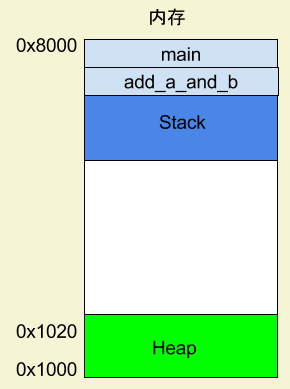
Once add_a_and_b finishes executing, its frame will be reclaimed, and the system will return to the point where the main function was interrupted, continuing execution. This mechanism allows for layered function calls, with each layer able to use its own local variables. All frames are stored in the Stack, and since frames are stacked on top of each other, the Stack is called a stack. Creating a new frame is referred to as “pushing” onto the stack, while reclaiming a stack is called “popping”. The characteristic of the Stack is that the last frame pushed is the first to be popped (because the innermost function call ends first), which is known as a “last in, first out” data structure. Each time a function execution ends, a frame is automatically released, and when all functions finish executing, the entire Stack is released.
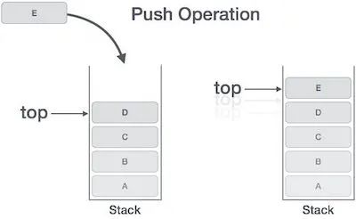
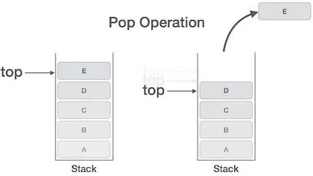
The Stack is allocated from the end address of the memory area, growing from higher addresses to lower addresses. For example, if the end address of the memory area is 0x8000, and the first frame is assumed to be 16 bytes, the next allocation will start from 0x7FF0; if the second frame is assumed to require 64 bytes, the address will move to 0x7FB0.
CPU Instructions
Example
After understanding registers and memory models, we can look at what assembly language actually is. Below is a simple program example.c.
int add_a_and_b(int a, int b) { return a + b;} int main() { return add_a_and_b(2, 3);}The gcc compiler converts this program into assembly language.
$ gcc -S example.cAfter executing the above command, a text file example.s will be generated, containing assembly language with dozens of lines of instructions. To put it simply, a simple operation in a high-level language may consist of several, or even dozens of CPU instructions at the low level. The CPU executes these instructions sequentially to complete the operation.
The simplified version of example.s is approximately as follows.
_add_a_and_b: push %ebx mov %eax, [%esp+8] mov %ebx, [%esp+12] add %eax, %ebx pop %ebx ret _main: push 3 push 2 call _add_a_and_b add %esp, 8 retAs can be seen, the two functions in the original program, add_a_and_b and main, correspond to the two labels _add_a_and_b and _main. Each label contains the CPU execution flow for that function.
Each line represents an operation executed by the CPU. It can be divided into two parts; let’s take one line as an example.
push %ebxIn this line, push is a CPU instruction, and %ebx is the operand used by this instruction. A CPU instruction can have zero to multiple operands. I will explain this assembly program line by line, and I recommend that readers copy this program into another window to avoid scrolling back up while reading.
Push Instruction
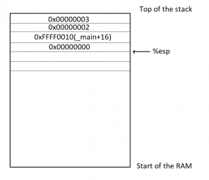
The program starts executing from the _main label, at which point a frame for main will be established on the Stack, and the address pointed to by the Stack will be written into the ESP register. If data needs to be written into the main frame later, it will be written at the address stored in the ESP register. Then, the first line of code begins execution.
push 3The push instruction is used to place an operand onto the Stack; here, it writes 3 into the main frame.
Although it seems simple, the push instruction actually has a preceding operation. It first retrieves the address in the ESP register, subtracts 4 bytes from it, and then writes the new address back into the ESP register. The subtraction is because the Stack grows from high to low addresses, and 4 bytes is because the type of 3 is int, which occupies 4 bytes. After obtaining the new address, 3 will be written into the first four bytes starting from this address.
push 2The second line is similar; the push instruction writes 2 into the main frame, right next to where 3 was written. At this point, the ESP register will again subtract 4 bytes (cumulatively subtracting 8).
Call Instruction
The call instruction in the third line is used to invoke a function.
call _add_a_and_bThe above code indicates a call to the add_a_and_b function. At this point, the program will look for the _add_a_and_b label and create a new frame for that function. The code for _add_a_and_b will then begin execution.
push %ebxThis line indicates that the value in the EBX register is written into the _add_a_and_b frame. This is because this register will be used later, so its value is retrieved first and will be written back after use. At this point, the push instruction will again subtract 4 bytes from the ESP register (cumulatively subtracting 12).
Mov Instruction
The mov instruction is used to write a value into a specific register.
mov %eax, [%esp+8]This line of code indicates that the address in the ESP register is increased by 8 bytes to obtain a new address, and then data is retrieved from the Stack at that address. Based on previous steps, it can be inferred that the value retrieved here is 2, which is then written into the EAX register. The next line of code does the same thing.
mov %ebx, [%esp+12]The above code retrieves data from the Stack at the address obtained by adding 12 bytes to the value in the ESP register; this time, it retrieves 3 and writes it into the EBX register.
Add Instruction
The add instruction is used to add two operands and write the result into the first operand.
add %eax, %ebxThe above code adds the value in the EAX register (which is 2) to the value in the EBX register (which is 3), resulting in 5, which is then written back into the first operand, the EAX register.
Pop Instruction
The pop instruction is used to retrieve the most recently written value from the Stack (i.e., the value at the lowest address) and write it into the specified location of the operand.
pop %ebxThe above code indicates that the most recently written value from the Stack (i.e., the original value of the EBX register) is retrieved and written back into the EBX register (since the addition is complete, the EBX register is no longer needed).
Note that the pop instruction also increments the address in the ESP register by 4, effectively reclaiming 4 bytes.
Ret Instruction
The ret instruction is used to terminate the execution of the current function and return control to the calling function. As can be seen, this instruction has no operands.
retWith the termination of the add_a_and_b function, the system returns to the point where the main function was interrupted, continuing execution.
add %esp, 8The above code indicates that the address in the ESP register is manually increased by 8 bytes and written back into the ESP register. This is because the ESP register points to the start address of the Stack, and the previous pop operation has already reclaimed 4 bytes; here, another 8 bytes are reclaimed, totaling the entire reclaim.
retFinally, the main function ends execution, and the ret instruction exits the program.