Microcontroller repair essentials! Use a digital multimeter to determine chip functionality in 3 steps, making it accessible for beginners.
Is troubleshooting microcontroller circuit boards difficult? The key is to check if the chip is damaged! With the current affordable prices of microcontroller chips, the focus of repair is not on the cost of replacement parts, but onaccurate judgment — Today, I will share practical tips from experienced repair technicians that can be accomplished using just a digital multimeter, without live operation, making it easy for beginners to get started!
1. Understand the core judgment logic of chip damage
Chip damage in microcontrollers essentially involves open or short circuits between external pins and internal circuits. The chip contains numerous PN junctions, and by using thediode measurement mode on a digital multimeter, you can quickly determine if the circuit is functioning normally by measuring the forward voltage drop across the PN junctions — this is the core principle of our repair process. Remember this logic, and the subsequent operations will follow naturally.
2. Key steps: Multimeter measurement operations + standard data
Preparation
Turn on the digital multimeter and set it todiode measurement mode. Connect the red probe to the ground of the microcontroller circuit, and use the black probe to sequentially touch each external pin of the chip.
Core measurement data (must remember!)
1. I/O pins: Normal display is 0.55–0.75V (corresponding to the forward voltage drop of the PN junction);
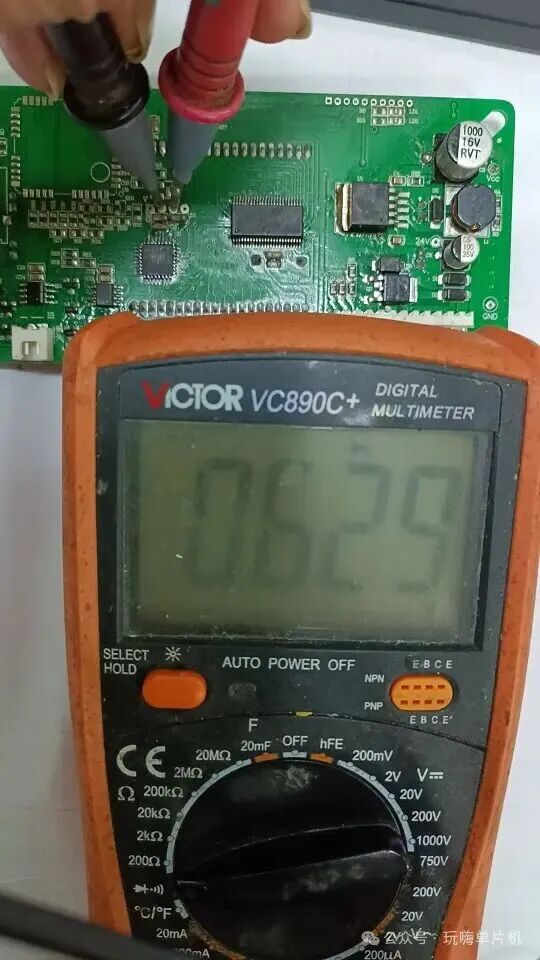
2. Power pins (VCC, VDD, etc.):
Switching power supply (secondary output high-frequency rectifier using Schottky like SS34, etc.):
Displays 0.18V–0.35V;
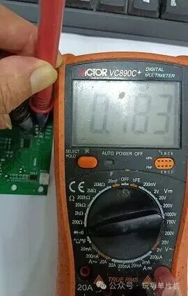
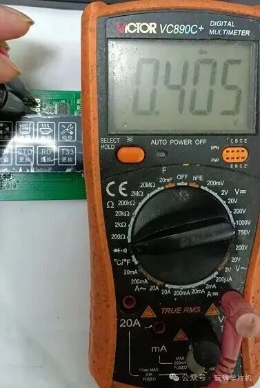
Linear voltage regulator (like 7805):Displays 0.35V–0.5V;
3. Clock / Reset pins: Normal display is 0.55–0.75V (consistent with I/O pin principles).
3. Common microcontroller fault repair guide: Targeted solutions for efficiency
1. Microcontroller circuit completely non-functional
First, check the three essential elements for the normal operation of digital logic chips: power supply, clock, and reset, focusing on whether the pins are open or shorted (open circuits show low current, short circuits can cause chip overheating).
① Measure power pins: A display of 0.18V–0.5V is normal; below 0.18V may indicate a power short circuit or internal chip short circuit, while above 0.5V indicates a power open circuit or internal chip open circuit;
② Measure clock / reset pins: A display of 0.55V–0.75V is normal; below 0.55V indicates a short circuit in the chip’s internal/external circuit, while above 0.75V indicates an open circuit in the chip’s internal pins.
2. Microcontroller circuit functioning abnormally
This type of fault is often related to power supply or signal abnormalities, and should be investigated in the following directions:
① Power abnormalities: Voltage too high/low may be due to faulty filter capacitors (causing voltage to rise) or load short circuits (pulling down voltage), or it may be due to open/poor grounding of the ground pin — when encountering unstable boards, first re-solder the external pins of the chip, as many faults can be resolved directly;
② Signal short circuits: Input signals (such as button signals) shorted to ground or to each other can interrupt or repeatedly execute the workflow. The diode measurement method described earlier can quickly verify and locate the problem.
4. Repair tips & pitfalls to avoid
1. When measuring, the red probe must be securely grounded, and the black probe should be tested pin by pin to avoid contact issues that could lead to data discrepancies; do not power the microcontroller board, and live operation is not required.
2. Do not only check the power circuit for power abnormalities; also investigate the filtering, decoupling, and load short circuits in the subsequent stages;
3. Internal short circuits in the chip can cause overheating; before measuring, you can touch the chip to visually assess if there are any abnormalities.
Repairing microcontroller circuit boards hinges on mastering the logic of “data comparison + observation of phenomena.” Remember these standard voltages and operational steps, and most faults can be quickly located. You can start measuring to verify right away. For friends who enjoy microcontroller development, what tricky problems have you encountered during repairs? Feel free to leave a comment and share; next time we will tackle more practical case studies! If you like it, don’t forget to follow and like!