The reliability design of microcontroller reset circuits
1. Overview
The factors affecting the operational stability of microcontroller systems can be roughly divided into external and internal factors:
1. External Factors
Radio frequency interference, which is transmitted in the form of spatial electromagnetic fields, induces corresponding interference in the conductors (wires or component pins) inside the machine. This type of interference can be attenuated through electromagnetic shielding and reasonable wiring/device layout;
Interference generated by the power line or within the power supply, which is coupled or directly conducted through the power line or components inside the power supply. This type of interference can be attenuated through power filtering, isolation, and other measures.
2. Internal Factors
The stability of the oscillation source is mainly determined by the start-up time, frequency stability, and duty cycle stability. The start-up time can be adjusted by circuit parameters, while stability is affected by the type of oscillator, temperature, voltage, and other parameters, all of which impact the reliability of the reset circuit.
2. Reliability Design of Reset Circuits
1. Basic Reset Circuit
The basic function of the reset circuit is to provide a reset signal when the system is powered on, until the system power is stabilized, at which point the reset signal is removed. For reliability, the reset signal must be removed after a certain delay even after the power stabilizes, to prevent jitter caused by power on/off or plugging/unplugging the power supply. The RC reset circuit shown in Figure 1 can achieve the above basic function, and Figure 3 shows its input-output characteristics. However, it cannot solve issues such as power glitches (Point A) and slow power drop (insufficient battery voltage), and adjusting the RC constant to change the delay may worsen drive capability. The circuit on the left has a high-level reset effective, while the right one has a low-level reset. Sm is the manual reset switch, and Ch can avoid interference from high-frequency harmonics on the circuit.
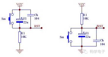
Figure 1 RC Reset Circuit
The reset circuit shown in Figure 2 adds a diode, which allows the capacitor to discharge quickly when the power voltage drops momentarily, ensuring reliable system reset even during a certain width of power glitches. The lower half of the input-output characteristics graph of the reset circuit shown in Figure 3 compares the effects of adding a discharge loop with the upper half.
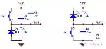
Figure 2 RC Reset Circuit with Discharge Loop
Using a comparator circuit not only solves the instability caused by power glitches but also reliably resets the system during slow power drops. Figure 4 is an example where when VCC x (R1/(R1+R2)) = 0.7V, Q1 turns off, causing the system to reset. The amplification effect of Q1 can also improve the load characteristics of the circuit, but the transition threshold voltage Vt is affected by VCC, which is a prominent drawback of this circuit. Using a voltage regulator diode can make Vt basically unaffected by VCC. See Figure 5, where when VCC is lower than Vt (Vz + 0.7V), the circuit resets the system.
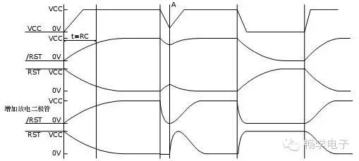
Figure 3 Input-Output Characteristics of RC Reset Circuit
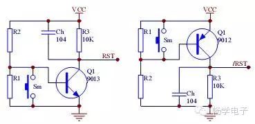
Figure 4 Reset Circuit with Voltage Monitoring Function
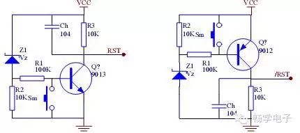
Figure 5 Stable Threshold Voltage
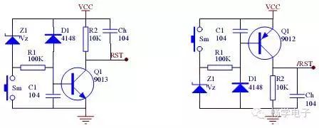
Figure 6 Practical Reset Monitoring Circuit
Based on this, adding a delay capacitor and discharge diode forms a well-performing reset circuit, as shown in Figure 6. Adjusting C1 can change the delay time, and adjusting R1 can modify the load characteristics, as shown in Figure 7, where the upper half corresponds to the characteristics of the circuit in Figure 5, and the lower half corresponds to Figure 6.
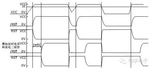
Figure 7 Input-Output Characteristics of Reset Circuit with Voltage Monitoring Function
2. Power Monitoring Circuit
The reset circuit with voltage monitoring mentioned above is also known as a power monitoring circuit. The monitoring circuit must have the following functions:
Power-on reset to ensure the system starts correctly upon power-up; Power-fail reset to reset the system when the power fails or the voltage drops below a certain value. There are similar integrated products on the market, such as the MAX809 and MAX810 produced by PHILIPS Semiconductor. These products are compact, low-power, and offer selectable threshold voltages. They ensure reliable reset of the system under various abnormal conditions, preventing system loss of control. The Rm and Sm in Figure 8 implement manual reset, and when this function is not needed, the Reset (or /Reset) terminal can be directly connected to the microcontroller’s RST (or /RST) terminal, greatly simplifying the peripheral circuit. The MAX708 from PHILIPS Semiconductor is also a good choice when manual reset functionality is not required.
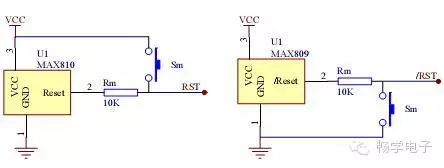
Figure 8 Integrated Reset Monitoring Circuit
Additionally, the MAX708 can monitor a second power signal, providing a voltage drop warning function for the processor. Using this function, the system can perform certain safety operations before resetting when the power drops, such as saving parameters, sending alarm signals, or switching to a backup battery. Figure 9 shows an application example of a power meter using the MAX708, which can save the current power reading to E2PROM before power glitches or outages, effectively solving the issue of lost power readings in E2PROM through multiple backup algorithms. When using this circuit, it is crucial to select an appropriate warning voltage point to ensure that the duration (tB) of the VCC voltage from the warning voltage to the reset voltage is long enough under energy storage conditions from the power supply (typically tB > 200ms is required to ensure stable data writing since the E2PROM write cycle is about 10-20ms). The method for adjusting the warning voltage involves adjusting R1 and R2 to make the PFI voltage 1.25V when VDC equals the warning voltage, at which point /PFO can be detected to confirm that the internal voltage comparator is functioning. Caution is needed during adjustment since this comparator is a window comparator. Figure 10 is the flowchart for this application.
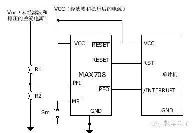
Figure 9 Typical Application of MAX708
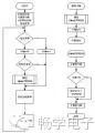
Figure 10 Flowchart for E2PROM Data Protection in Power Meter Application
3. Multifunctional Power Monitoring Circuit
In addition to power-on reset and power-fail reset, many monitoring circuits integrate necessary functions for the system, such as:
Power measurement and control, providing warning indications or interrupt request signals when the supply voltage is abnormal, facilitating the system’s handling of exceptions; Data protection, performing necessary protections for data when the power or system operates abnormally, such as write protection, data backup, or switching to a backup battery; Watchdog timer, resetting the system when the program “runs away” or “hangs”; Other functions, such as temperature measurement and short-circuit testing, etc.
We refer to this as a multifunctional power monitoring circuit. Below are two particularly suitable multifunctional monitoring circuits widely used in industrial control, security, and financial sectors:
The CAT1161 from Catalyst is an integrated 16K bit E2PROM (I2C interface) that incorporates a watchdog timer, voltage monitoring, and reset circuit. Not only is it highly integrated and low power (the E2PROM part achieves true zero power in static conditions), but the watchdog timer is implemented by changing the level of SDA, saving system I/O resources. The threshold voltage can be modified via a programmer, covering the vast majority of applications. When the power drops below the threshold voltage, hardware access to the E2PROM is prohibited, ensuring data safety.
Note that the RST and /RST pins are I/O pins, and the CAT1161 generates a reset signal if it detects any voltage anomalies on either pin. The pull-down resistor R2 and pull-up resistor R1 connected to the RST /RST pins must be connected simultaneously; otherwise, the CAT1161 will continuously generate resets! Similarly, if manual reset functionality is not required, the two components Rm and Sm can be saved.
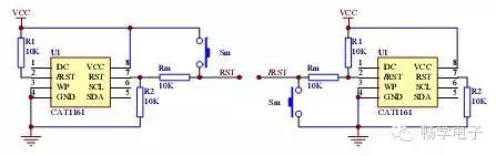
Figure 11 Interface Circuit of Built-in WDT RESET /RESET E PROM Monitoring Device
The SA56600-42 from PHILIPS is designed to protect the data of SRAM in microcomputer systems during power voltage drops or outages. When the power voltage drops to the normal value of 4.2V, the output CS goes low, pulling CE low, thus prohibiting operations on the SRAM. Simultaneously, a low-level active reset signal is generated for system use. If the power voltage continues to drop to a normal value of 3.3V or lower, the SA56600-42 switches the system’s power supply from the main power to a backup lithium battery. When the main power returns to normal (voltage rises to 3.3V or higher), the power supply to the SRAM switches back from the backup lithium battery to the main power. When the main power exceeds the typical value of 4.2V, the output CS goes high, enabling operations on the SRAM, with the reset signal persisting until the system returns to normal operation. This device reliably protects the data in the SRAM during insufficient system power voltage or sudden power outages.
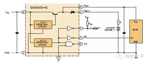
Figure 12 Typical Application of SA56600-42 with Built-in SRAM Data Protection Circuit
4. Reset Circuit Design for ARM Microcontrollers
Whether in mobile phones, high-end handheld devices, or embedded systems, 32-bit microcontroller ARM is occupying an increasing share of the market, becoming the de facto high-end industrial standard. Due to ARM’s high speed, low power consumption, and low operating voltage, its noise tolerance is low, posing a challenge to the limits of digital circuits, and raising higher requirements for power ripple, transient response performance, clock source stability, and power monitoring reliability.
Monitoring technology for ARM is complex and very important.
Monitoring circuits implemented with discrete components are greatly affected by external factors such as temperature, humidity, and pressure, and the impact on different components is inconsistent. Large board areas and excessively long pins can easily introduce radio frequency interference, and high power consumption is also unacceptable for many applications. Integrated circuits can effectively solve these issues. Currently, many microprocessors have integrated monitoring circuits, but due to manufacturing costs and process technology reasons, most of these monitoring circuits are implemented using low-voltage CMOS technology, which still lags behind specialized monitoring circuits made with high-voltage, high-linearity bipolar technology.
The conclusion is that using ARM without dedicated monitoring circuits may lead to more problems than it solves. Experience tells us that using dedicated monitoring circuits can avoid many strange problems. ARM application engineers should remember to avoid unnecessary detours!
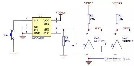
Figure 13 Practical and Reliable ARM Reset Circuit Implemented with PHILIPS MAX708
Figure 13 shows a practical and reliable ARM reset circuit. The working voltage of the ARM core is low. R1 ensures that the voltage remains below the operating power of MAX708 for reliable resets. The TRST signal is used for the JTAG interface. Using HC125 can realize multiple reset sources for ARM, such as resetting ARM via a PC serial port or JTAG interface.