With the rapid development of the times, the monitor market has begun to flourish, and it seems that everyone owns a monitor. However, during use, some faults may occur. How can we identify which components are problematic and how to resolve them?
1. Delay Fuse
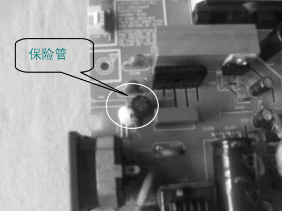
Connect the red and black probes of the multimeter to the two solder points of the fuse. Observe whether the reading on the multimeter is 0Ω. If the resistance is 0Ω, it indicates that the fuse is normal. Otherwise, the fuse is burnt inside.
2. Varistor
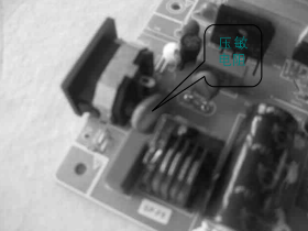
Connect the red and black probes of the multimeter to the two solder points of the varistor. Observe whether the reading on the multimeter is infinity. If the resistance is infinity, it indicates that the varistor is intact. Otherwise, the varistor has been punctured.
3. EMI Filter Capacitor
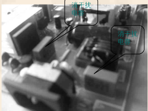
Connect the red and black probes of the multimeter to the two pins of the EMI filter capacitor. If the pointer of the multimeter shows a large swing and then slowly returns to infinity, it indicates that the charge and discharge performance of the EMI filter capacitor is good. If the pointer does not move or does not return after moving, it indicates that the EMI filter capacitor is open or punctured. If the pointer suddenly returns to infinity during the return process, it indicates that the capacitor is leaking.
4. EMI Filter Inductor
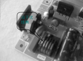
Connect the red and black probes of the multimeter to the two solder points of the inductor winding. Observe whether the reading on the multimeter is 0.1Ω. If the resistance is 0.1Ω, it indicates that the inductor is normal.
5. Thermistor
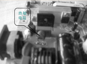
Connect the red and black probes of the multimeter to the two solder points of the fuse. Observe whether the reading on the multimeter is 3Ω. If the resistance is 3Ω, it indicates that the thermistor is normal. Otherwise, the fuse is burnt inside.
6. Bridge Rectifier Module
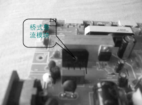
Connect the red probe of the multimeter to the “+” terminal of the bridge rectifier module and the black probe to the “~” terminal. The measured resistance value is the forward resistance, which should be around 1.2K. Swap the probes, connecting the black probe to the “+” terminal and the red probe to the “~” terminal. The measured resistance is the reverse resistance, which should be infinity.
Connect the black probe of the multimeter to terminal “1” of the bridge rectifier module and the red probe to the “~” terminal. The measured resistance is the forward resistance, which should be around 1.2K. Swap the probes, connecting the red probe to terminal “1” and the black probe to the “~” terminal. The measured resistance is the reverse resistance, which should be infinity.
7. +300V Filter Capacitor
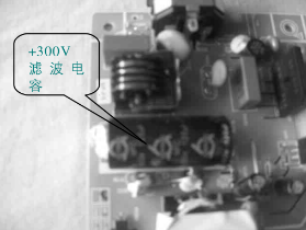
Connect the red and black probes of the multimeter to the two pins of the filter capacitor. If the pointer of the multimeter shows a large swing and then slowly returns to infinity, it indicates that the filter capacitor’s charge and discharge performance is good. If the pointer does not move or does not return after moving, it indicates that the filter capacitor is open or punctured. If the pointer suddenly returns to infinity during the return process, it indicates that the capacitor is leaking.
8. Switching Power Supply Control Module
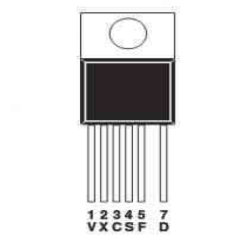
Taking the switching power supply control module TOP257YN as an example:
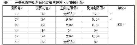
Connect the red probe of the multimeter to pin 4 (ground pin) of the module and measure the resistance of other pins sequentially with the black probe. The measured resistance value is the forward resistance. Swap the probes, connecting the black probe to pin 4 (ground pin) and measuring the resistance of other pins with the red probe. The measured resistance value is the reverse resistance. The measured forward and reverse resistance values are shown in the table:
9. Switching Transformer
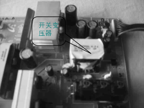
Connect the red and black probes of the multimeter to the two solder points of the primary winding. Observe whether the reading on the multimeter is 0.2Ω. If the resistance is 0.2Ω, it indicates that the primary winding is normal.
Set the multimeter to the R×1Ω range and zero it, then connect the red and black probes to the two solder points of the secondary winding. Observe whether the reading on the multimeter is 0.1Ω. If the resistance is 0.1Ω, it indicates that the secondary winding is normal. If the multimeter shows zero or infinity, it indicates that the secondary winding is short-circuited or open-circuited.
10. Composite Rectifier Diode
Connect the black probe of the multimeter to pin 1 of the composite rectifier diode and the red probe to pin 2. The measured resistance value is the forward resistance, which should be around 500Ω. Swap the probes, connecting the red probe to pin 1 and the black probe to pin 2. The measured resistance value is the reverse resistance, which should be infinity. If both the forward and reverse resistance values are zero, it indicates that the composite diode has broken down.
Connect the black probe of the multimeter to pin 3 of the composite rectifier diode and the red probe to pin 2. The measured resistance value is the forward resistance, which should be around 500Ω. Swap the probes, connecting the red probe to pin 3 and the black probe to pin 2. The measured resistance value is the reverse resistance, which should be infinity. If both the forward and reverse resistance values are zero, it indicates that the composite diode has broken down.
11. Optocoupler
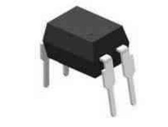
Connect the black probe to the positive terminal of the internal LED of the optocoupler and the red probe to the negative terminal. The measured resistance value is the forward resistance. Conversely, swapping the probes will measure the reverse resistance. If both the forward and reverse resistance values are zero, it indicates that the optocoupler has broken down.
This article is an original piece by Yi Education. Please indicate the source when reprinting!