▼Click the card below to follow our public account ▼Although online PCB manufacturing has become very fast and inexpensive, with some manufacturers offering free test board production, sending out for board fabrication still takes too long compared to making test circuit boards in “one minute”.For circuits that need testing, rapid prototyping allows for quick iterations to complete experimental circuits. The final official circuit board can be produced by a formal manufacturer.The following outlines the specific process from rapid prototyping to soldering completion:1. Design the PCB circuit board: 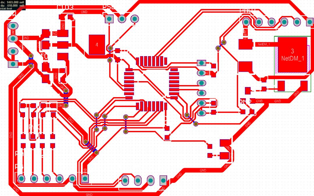 2. Set to print only the TOP LAYER and the via layer
 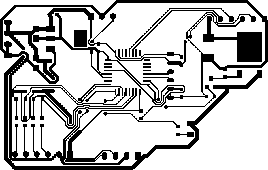 3. Use a laser printer to print on thermal transfer paper
 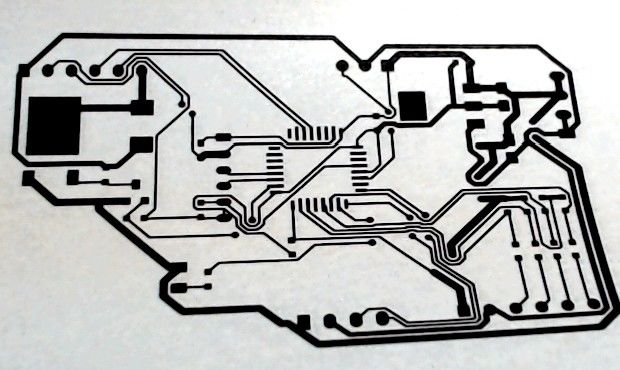 4. The thinnest trace on this circuit board is set to 10 mil
 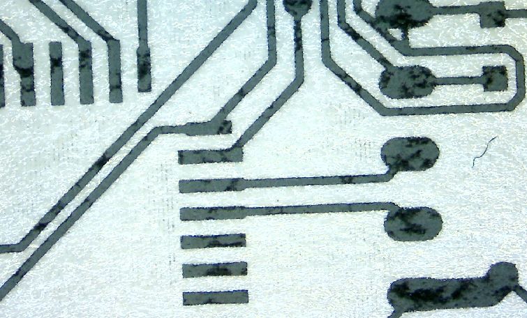 5. The one-minute prototyping time starts from when the laser printer prints the black and white circuit on the thermal transfer paper.
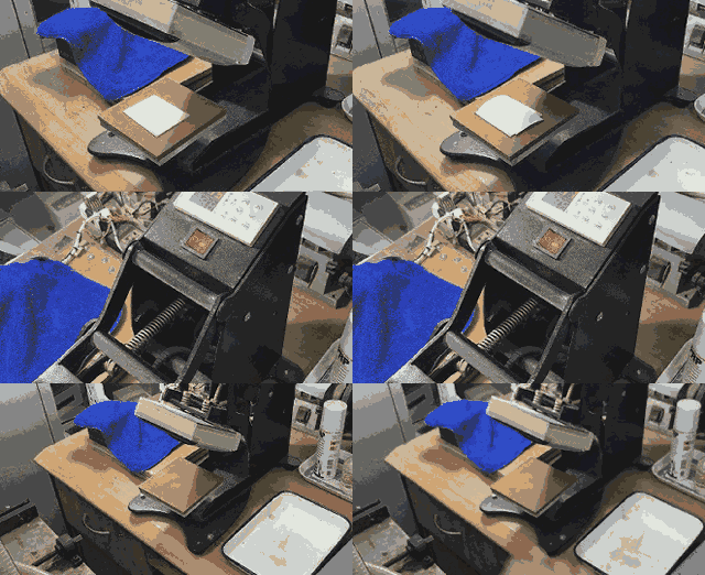
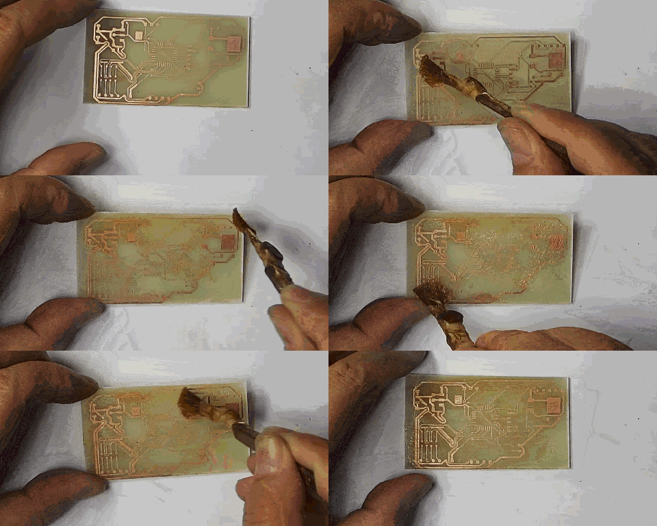
 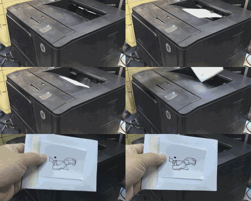 6. For single-sided circuit boards, one sheet is sufficient.Then attach it to a suitably sized copper-clad board, and under the heat and pressure of the thermal transfer machine, the thermal transfer can be completed in 20 seconds. Remove the copper-clad board, peel off the thermal transfer paper, and you can see the clear circuit diagram on the copper-clad board.
  7. Then place the copper-clad board in the oscillating etching tank, using a mixture of hydrochloric acid and hydrogen peroxide as the etching solution, which only takes 15 seconds to remove the excess copper layer.
 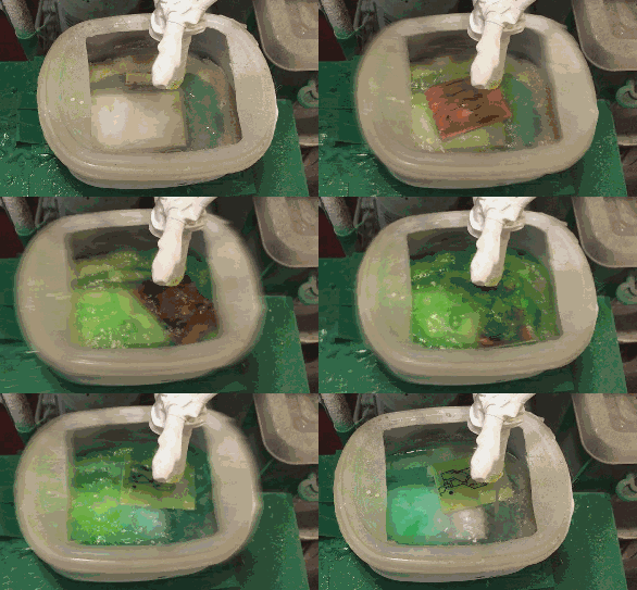 The appropriate ratio of hydrochloric acid to hydrogen peroxide and the high-speed oscillating etching tank are key to achieving rapid and perfect etching.After rinsing with water, the etched circuit board can be taken out. At this point, a total of 45 seconds have passed. Never recklessly touch high-concentration etching solutions. Otherwise, the pain you experience will be remembered for a lifetime.8. Then use acetone to wipe off the black toner, and thus, an experimental PCB board is completed.
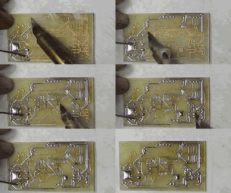
 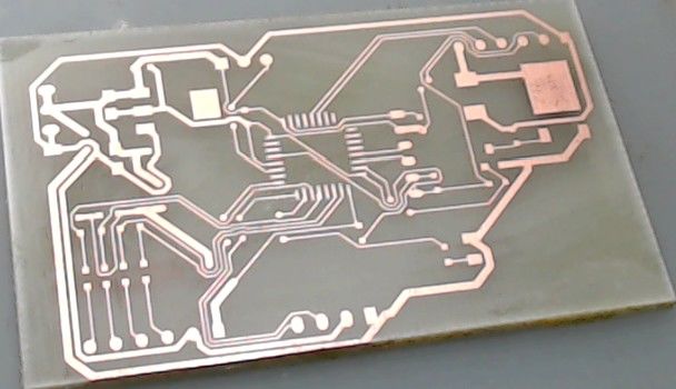 9. Apply flux on the surface of the circuit board
  10. Use a wide-tipped soldering iron to tin the circuit board, facilitating subsequent soldering
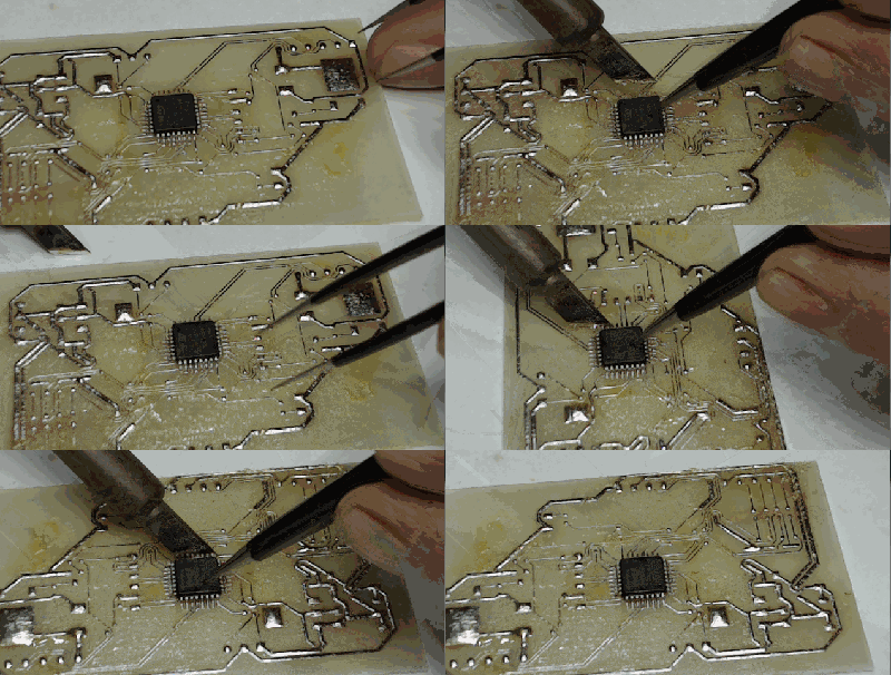
  11. Remove the flux, apply soldering flux for surface mount components, and complete the component soldering
 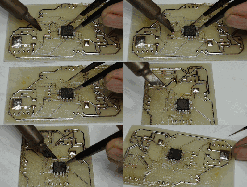 12. Due to the pre-coated solder, soldering components is relatively easy
  13. After soldering, use board cleaning solution to clean the circuit board
 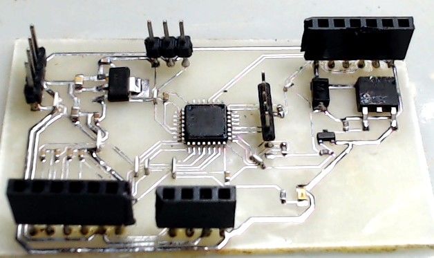 14. A close-up of the circuit board
 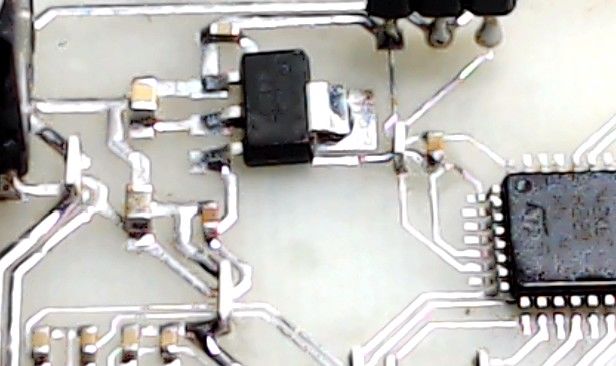 15. The circuit board has multiple short jumpers 16. The jumpers are completed using 0603, 0805, and 1206 zero-ohm resistors
 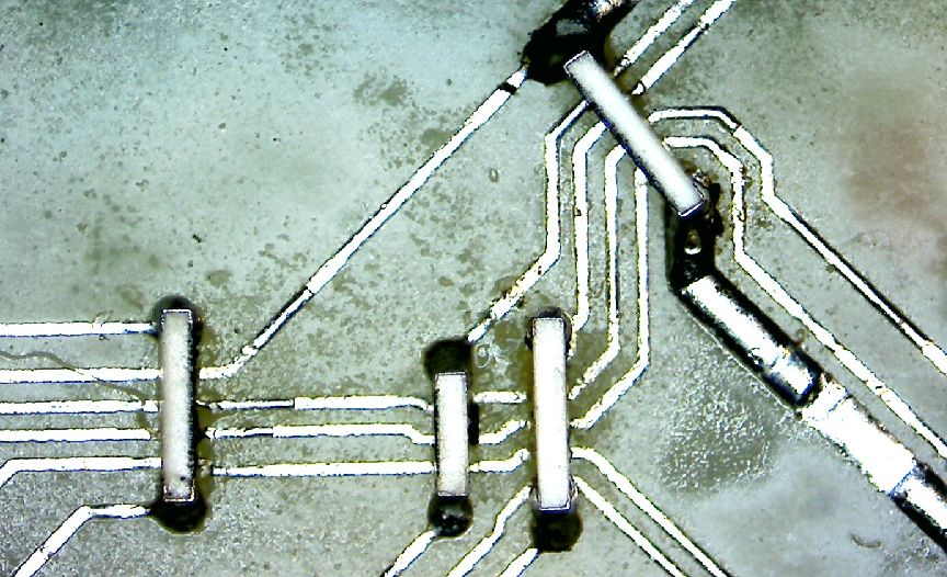 17. After ten minutes, the circuit board can be tested
 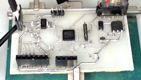 18. The circuit board during the testing process
 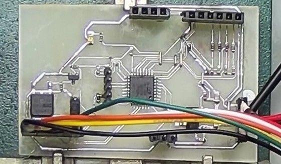 19. Completing the circuit debugging
 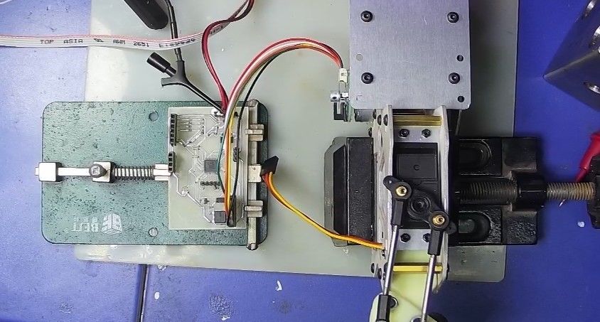 The one-minute thermal transfer prototyping method can make hardware production as convenient as software programming. Once the circuit blocks are tested, the final circuit can be produced using formal prototyping methods.This method not only saves experimental costs but, more importantly, saves time. A good idea, if it follows the normal prototyping cycle, would take one or two days to receive the circuit board, which can diminish the excitement.
Disclaimer:This account maintains neutrality regarding all original and reprinted articles’ statements and viewpoints. The articles are provided for readers’ learning and communication. The copyright of the articles, images, etc., belongs to the original authors. If there is any infringement, please contact us for deletion.

 【Tutorial】Electronic Components【Tutorial】Fundamentals of Analog Electronics【Tutorial】Fundamentals of Digital Electronics【Tutorial】Circuit Theory
【Tutorial】Electromagnetic Compatibility
【Tutorial】Principles and Applications of Microcontrollers
【Tutorial】Basics of C Language
【Tutorial】Real-Time Operating System uCOS-II
【Tutorial】Basics of ARM
【Resources】20 Smart Home System Design Resources
【Resources】400+ Animated Electronic Circuit Courseware + 147G Hardware Design and Development Video Resources
【Resources】100+ Switching Power Supply Design Resources
【Resources】800+ Microcontroller Design Resources, Master Microcontroller Circuit Design~
【Resources】10G+ AD Packaging Library Files, Meeting 99% of Your Development Needs!
【Resources】60+ Inverter Power Supply Resources, Supporting New Energy Application Development
【Resources】31 Flyback Parameter Automatic Calculation Formula Tables
【Resources】176 Power MOSFET Circuit Learning Resources
【Resources】97 Switching Power Supply Loop Control Design Resources
【Resources】525 Microcontroller C Language Simulation Examples
【Resources】5 Sets of DC Brushless Three-Phase Motor Control Solutions
【Resources】1399 Cadence PCB Operation Manuals and Packaging Library Files

 Read the original textGet more learning resources