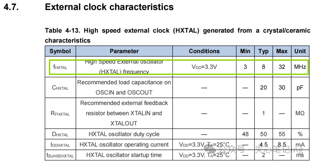
1. First, identify the clock pins.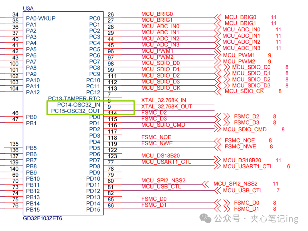 Provides a 32.768kHz clock.How is 32.768kHz derived? Refer to the chip manual. Typically, a nominal value is used.High-speed clock:
 Low-speed clock:
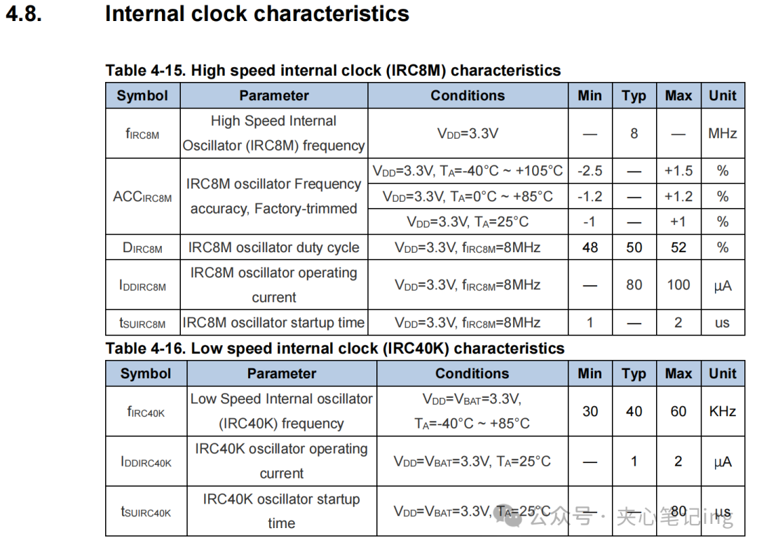
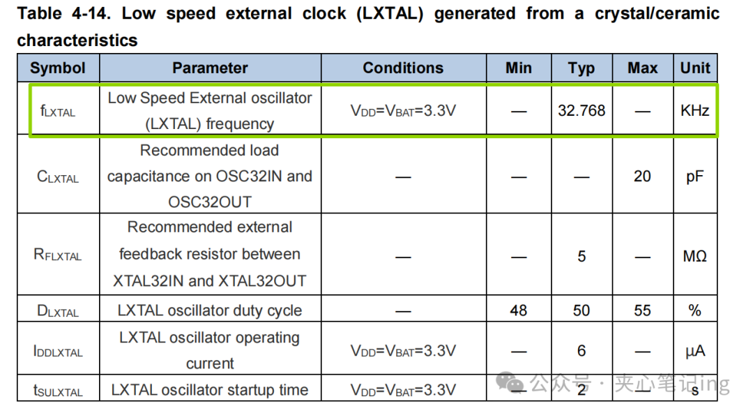 The low-speed clock is generally used for the RTC module. Its main function is timing.32.768kHzis exactly 2 to the power of 15, making it easy to divide down to whole seconds.1 second corresponds to 1Hz.Internal clock: lower accuracy.
 Crystal oscillator accuracy, if displayed as ±20ppm, means an accuracy of 20 parts per million.
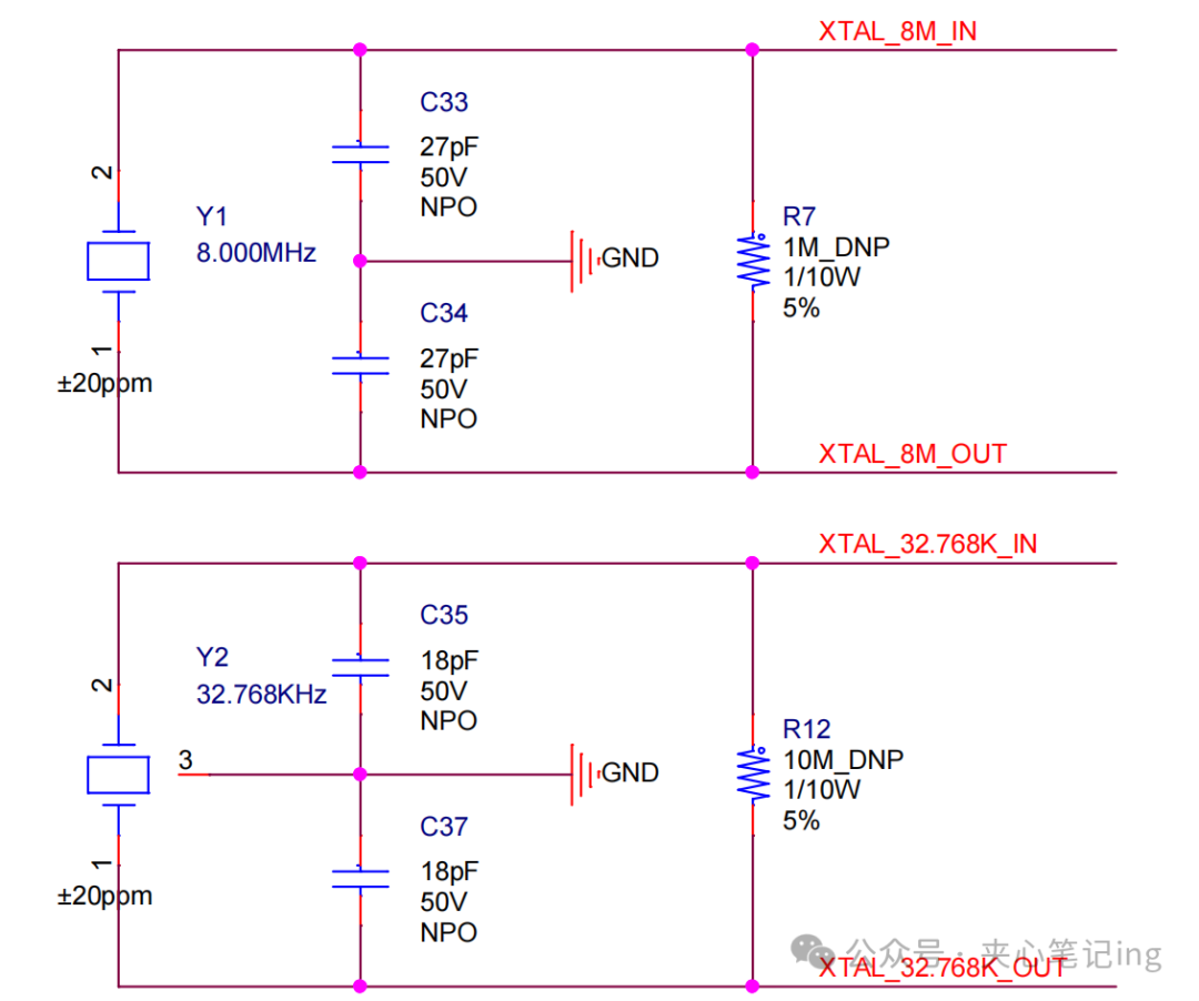 The crystal oscillator also needs to be paired with matching capacitors; the specific capacitance required will be indicated in the crystal oscillator’s datasheet.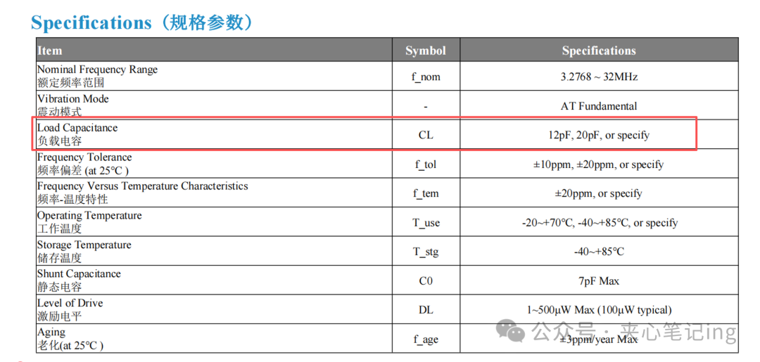

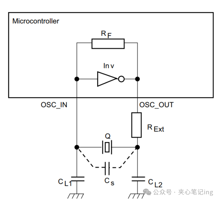
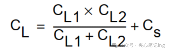 Stray capacitance is unquantifiable and can only be roughly estimated: 3~5pF.CL1=CL2Assuming the datasheet specifies CL=20pF,take CS=5pF.Then calculateCL1=CL2=30pF, which means a load capacitance close to 30pF should be used for this crystal oscillator.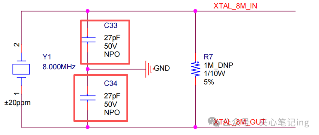
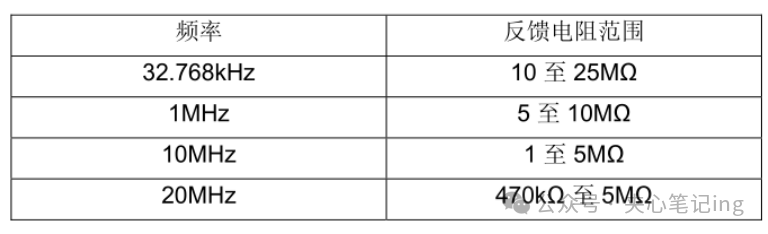 The feedback resistor can be reserved in position but not soldered.