 The traffic light plays an important role in our daily lives, but controlling a traffic light is not complicated. This experiment will teach you how to use Arduino to simulate the control of a traffic light.1. Experiment Materials 1. Arduino development board ×1 2. Traffic light module ×1 3. Breadboard ×1
4. Dupont wires (male to male) × several
5. USB data cable ×1
2. Experiment Principle2.1 Traffic Light A traffic light typically consists of three colored indicators: red, yellow, and green. Different colored indicators convey different traffic instructions: (1) Red light – Stop (2) Green light – Go (3) Yellow light – Transition reminder (indicates that the signal is about to change)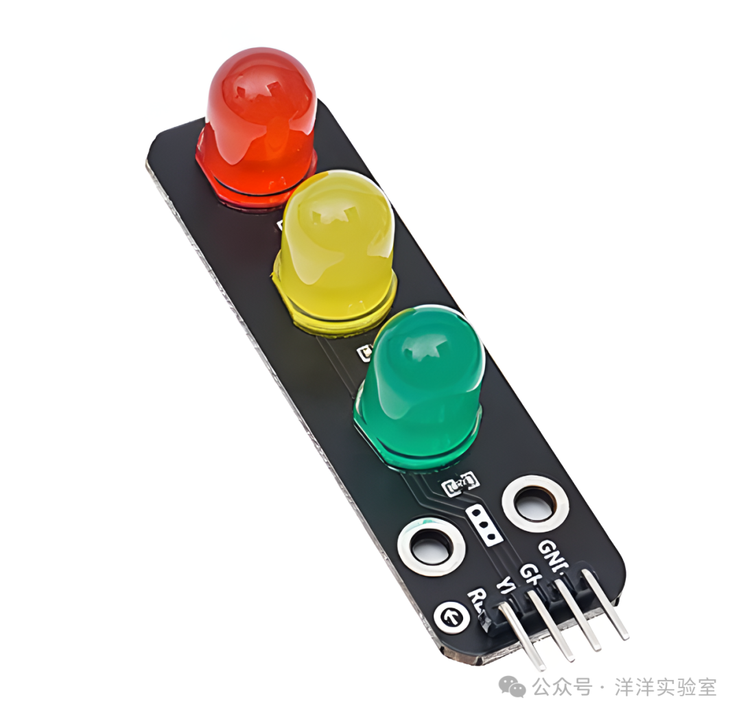
The traffic light module used in this experiment consists of three high-brightness LEDs (red, yellow, green) and current-limiting resistors. By outputting high and low level signals from the Arduino UNO development board, we can control the on/off state and duration of each colored LED, simulating the working sequence of a real traffic light.
3. Experiment Content
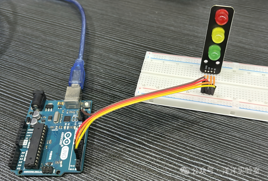
First, correctly place the traffic light module on the breadboard and use Dupont wires to complete the following connections:
| Traffic Light Module | Arduino UNO |
| GND | GND |
| RE | Digital Pin 2 |
| YE | Digital Pin 3 |
| GE | Digital Pin 4 |
Next, write and upload the Arduino program. The program code is as follows:
// Pin definitions
#define PIN_RED     2
#define PIN_YELLOW  3
#define PIN_GREEN   4

// Time constants (in milliseconds)
#define GREEN_DURATION   5000  // Green light on for 5 seconds
#define YELLOW_SOLID     2000  // Yellow light solid for 2 seconds
#define YELLOW_BLINK     300   // Yellow light blink interval 300 milliseconds
#define RED_DURATION     5000  // Red light on for 5 seconds

void setup() {
  // Initialize pins as output mode
  pinMode(PIN_RED, OUTPUT);
  pinMode(PIN_YELLOW, OUTPUT);
  pinMode(PIN_GREEN, OUTPUT);
}

void loop() {
  // Stage 1: Green light on for 5 seconds
  digitalWrite(PIN_RED, LOW);
  digitalWrite(PIN_YELLOW, LOW);
  digitalWrite(PIN_GREEN, HIGH);
  delay(GREEN_DURATION);

  // Stage 2: Yellow light solid for 2 seconds, then blink for 3 seconds (5 times total)
  digitalWrite(PIN_GREEN, LOW);
  digitalWrite(PIN_YELLOW, HIGH);
  delay(YELLOW_SOLID);

  // Yellow light blinking
  for (int i = 0; i < 5; i++) {
    digitalWrite(PIN_YELLOW, LOW);
    delay(YELLOW_BLINK);
    digitalWrite(PIN_YELLOW, HIGH);
    delay(YELLOW_BLINK);
  }

  // Stage 3: Red light on for 5 seconds
  digitalWrite(PIN_YELLOW, LOW);
  digitalWrite(PIN_RED, HIGH);
  delay(RED_DURATION);
}
After uploading the program, observe the operation of the traffic light module.