What is a Phased Array Antenna?
In simple terms, a phased array antenna is an advanced antenna system that electronically controls the direction of the beam without physically moving the antenna.
The core components consist of multiple independent antenna elements (radiating elements) arranged in a specific pattern (array), each connected to a phase/amplitude controller (usually a phase shifter).
1. Core Working Principle: Wave Interference
The working principle of a phased array antenna is based on the physics of beamforming and coherent interference.
-
Constructive Interference: When the peaks of two or more waves meet, they superimpose, enhancing the signal.
-
Destructive Interference: When the peak of one wave meets the trough of another, they cancel each other out, weakening the signal.
The phased array manipulates this interference effect by precisely controlling the phase (i.e., the relative delay in time) at which each antenna element transmits or receives signals.
Assuming we have a row of antenna elements and want to direct the beam to the right.
1. Simultaneous Emission: If all elements emit signals simultaneously, the wavefront will form a plane, with the beam direction perpendicular to the array, pointing straight ahead.
2. Sequential Delayed Emission: If we let the leftmost element emit first, and then each subsequent element emits with a slight delay, the wavefronts will superimpose to form a tilted wavefront, directing the beam to the right.
3. Electronic Phase Control: In practical phased arrays, this “delay” is controlled by phase shifters. By applying a specific phase shift to the signal of each antenna element, the same effect can be achieved electronically, allowing the beam to “steer” in space.
By precisely controlling the phase of each element in real-time via a computer, the beam can be scanned, jumped, and shaped in a very short time.
2. Key Technical Features and Advantages
Compared to traditional mechanically scanned antennas, phased array antennas have revolutionary advantages:
1.<span>Inertia-free Electronic Scanning</span>
Extremely fast: Beam steering occurs at the speed of electromagnetic waves, almost completed in microseconds or nanoseconds, capable of tracking multiple targets simultaneously or quickly switching between multiple directions. High flexibility: Multiple independent beams can be generated to perform various tasks such as search, tracking, and communication simultaneously.
2.<span>High Reliability and Redundancy</span>
Even with hundreds or thousands of antenna elements, if a few elements fail, the system performance will only slightly degrade rather than completely fail, achieving “graceful degradation”.
3.<span>Multifunctionality</span>
The same antenna can be used for multiple functions such as radar, electronic warfare, and communication, making it the core of modern military platforms (such as warships and aircraft) to achieve an “integrated RF system”.
4.<span>Strong Concealment and Anti-jamming Capability</span>
The beam can be designed to be very narrow and energy-concentrated, making it difficult for enemies to intercept (low probability of intercept).
It can quickly align the null (the area of very weak signal) towards the direction of the interference source, effectively suppressing the interference.
5.<span>Long Lifespan</span>
Eliminating bulky and failure-prone mechanical rotation structures greatly improves reliability.
Of course, it also has disadvantages:
-
High Cost: The large number of elements, phase shifters, T/R components, and complex signal processing systems lead to high manufacturing costs.
-
System Complexity: Difficulties in design and calibration.
-
Power Consumption and Heat Dissipation: Especially for active phased arrays, a large number of T/R components generate significant heat during operation.
3. Main Types
Phased array antennas are mainly divided into two categories:
1. Passive Phased Arrays
These have only one central transmitter and receiver. The phase shifters are located between the antenna elements and the central transceiver to control the beam direction. The structure is relatively simple and cost-effective, but functionality and reliability are inferior to active phased arrays.
2. Active Phased Arrays
This is the current mainstream and high-end technology. Each antenna element (or sub-array) is directly connected to a complete T/R component, which includes a miniaturized transmitter, receiver, phase shifter, and amplifier.
Advantages:
-
Higher reliability (distributed transmission sources, minimal impact from individual component failures).
-
Higher efficiency (minimal signal loss during amplification).
-
More flexible functionality (such as adaptive beamforming).
-
Performance far exceeds that of passive phased arrays.
4. Antenna Element Components
Antenna elements are used to transmit/receive electromagnetic waves from the transceiver module to free space. They are typically arranged in a grid pattern or mounted on surfaces to radiate energy efficiently. Satellite ground stations need to have dual-polarization capability, supporting both left-hand circular polarization (LHCP) and right-hand circular polarization (RHCP) simultaneously.
However, achieving high isolation in cross-polarized dual-polarization antenna elements is not easy. The most classic dual-polarized antennas, such as crossed dipoles and crossed slot antennas, are achieved by replicating a radiating element and placing it at a right angle to the original element. In recent years, patch antennas excited by two orthogonal modes have also become very popular, with each mode corresponding to a separate polarization.
5. T/R Components
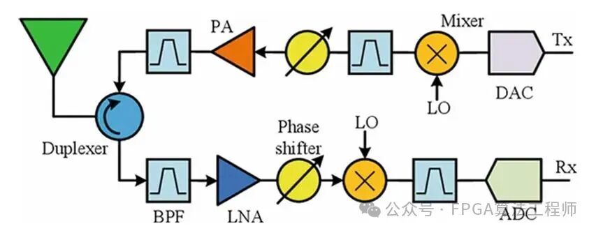
T/R components are often regarded as the most critical part, accounting for about half of the overall cost of phased array antennas. Over the past few decades, T/R modules have undergone significant changes in materials, design, and layout technology. Figure 1 shows a typical layout of modern T/R modules. It includes several basic components such as duplexers, filters, phase shifters, power amplifiers, low-noise amplifiers (LNA), mixers, local oscillators (LO), analog-to-digital converters (ADC), and digital-to-analog converters (DAC).
Duplexer
As a satellite ground station, full-duplex communication is required to simultaneously perform uplink and downlink with the satellite. This is achieved using a component called a duplexer (or circulator). It isolates the receive path from the transmit path while allowing them to share a common antenna element, suppressing interference.
Filter
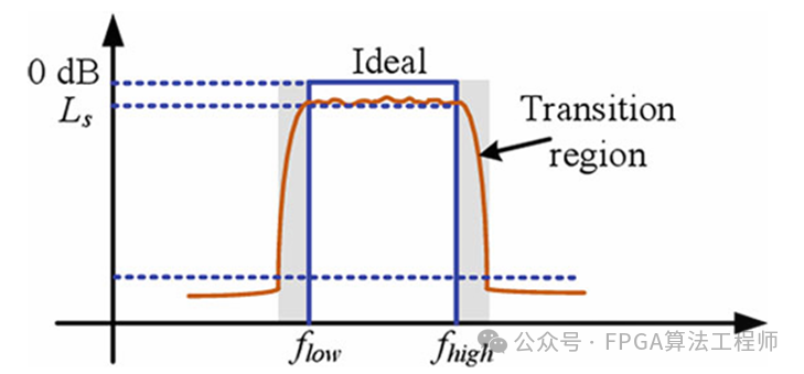
A filter is a frequency-selective component that allows signals through a specific frequency band while suppressing signals outside that band. For example, the filter following the duplexer in the receive path is a bandpass filter (BPF), which allows received signals to pass while attenuating transmitted signals that leak and couple from the transmit path. This is particularly important for satellite communication applications, as they operate in frequency multiplexing, while radar applications use time-division multiplexing. Figure 2 shows the transfer function of a typical bandpass filter. Ideally, it is expected to pass signals within a certain frequency range and completely eliminate out-of-band signals. The insertion loss of the filter indicates the level of attenuation within the passband. There is a gradual transition region between the passband and the suppression region. The goal of filter design is to provide a steep transition while maintaining acceptable insertion loss.
Power Amplifier (PA)
The power amplifier is used to amplify the input signal before it is transmitted to free space through the antenna elements. Due to the nonlinearity of power amplifiers, they produce various distortions of output signals, including harmonic distortion and intermodulation products.
Low Noise Amplifier (LNA)
The main function of the LNA is to amplify the signals received from the antenna elements and then send them to subsequent components such as mixers and filters. Each component in the receive path adds additional noise to the signal. The output signal-to-noise ratio () of a given device will be less than the input signal-to-noise ratio (). This noise figure F describes the signal-to-noise ratio loss caused by the device.
The overall noise figure of cascaded components is given by the following formula:
where is the noise figure, and is the gain of the th component.
This equation indicates that in RF cascades, the first component determines the final noise figure of the system. This means that all passive components (such as cables and filters) located before the first amplifier negatively impact the noise figure. Similarly, components following high-gain amplifiers have minimal impact on the overall noise figure. For high-performance low-noise amplifiers (LNA), which have relatively low noise figures and high gain, the total noise figure is primarily determined by the first component, the LNA. To achieve good link sensitivity, the LNA must be placed as close to the antenna elements as possible.
Phase Shifter
The phase shifter is used to change the phase of the signal. An ideal phase shifter should have low and approximately equal insertion loss across all phase states. The phase shift is a constant relative to frequency, so phase shifters are typically used for narrowband beamforming. For wideband beamforming, true time delay (TTD) units are required, where the delay is a linear function of frequency.
Mixing and Local Oscillator
The local oscillator (LO) generates the desired frequency using a phase-locked loop (PLL) combined with a crystal oscillator. In the receive (Rx) link, the mixer is used to downconvert the input signal from the radio frequency (RF) band to the intermediate frequency (IF) band. In the transmit (Tx) link, the mixer is used to upconvert the output signal from the intermediate frequency (IF) band to the radio frequency (RF) band. The output of the mixer is the sum and difference frequencies of the two input signals. A second bandpass filter (BPF) following the mixer is used to select the desired difference frequency component and minimize any intermodulation products generated by mixing. This heterodyne carrier frequency conversion has been well validated in engineering practice and has been used for many years. However, to maintain the desired wide bandwidth, many filters are still required. Nowadays, mixers and frequency conversion processes are not strictly necessary. Direct sampling methods allow for direct sampling of RF signals, achieving a larger input bandwidth.
AD/DA
ADC is used to convert signals from the analog domain to digital samples, while DAC performs the reverse process. The dynamic range of the ADC is determined by the effective number of bits N:
This gives the maximum dynamic range achievable when the signal level is at the ADC full-scale value. Note that the effective number of bits N is used in the calculation because it accounts for non-ideal factors in the ADC that limit the achievable bits. The sampling clock synchronization of ADC and DAC must be carefully designed to minimize timing discrepancies. For analog beamforming and sub-array level digital beamforming, signals from multiple antenna elements are combined before digitization to reduce the number of ADCs and DACs. In unit-level digital beamforming, each antenna element has its own ADC and DAC. Such a high level of digitization can enhance functionality and provide better performance compared to its predecessors.
6. FPGA Applications in Phased Arrays
FPGAs are typically located at the front end of digital beamforming and processing in phased array systems, undertaking the following core tasks:
1. Digital Beamforming – The Core Function
This is the primary task of the FPGA in both receive and transmit modes.
Receive Beamforming:
The analog signals received by each antenna element are downconverted and converted to digital signals by the ADC.
These digital signal streams are fed into the FPGA in parallel.
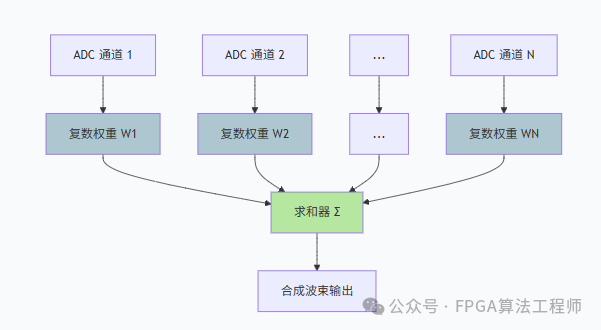
The FPGA applies a complex weight calculated by the beam control computer for each channel. This weight includes the phase shift and amplitude weighting required to point in a specific direction (to reduce sidelobes).
The FPGA aligns and sums all the weighted channel data to form one or more beams directed towards specific directions.
Transmit Beamforming:
A raw signal is sent to the FPGA.
The FPGA duplicates this signal and applies a specific pre-phase and amplitude weight for each transmit channel.
The weighted digital signal streams are sent to their respective DACs, converted to analog signals, and then upconverted and amplified before being radiated by the antenna. These signals interfere in space, forming a transmit beam directed towards the predetermined direction.
2. Calibration and Compensation
The performance of the phased array highly depends on the consistency of all channels. However, due to manufacturing tolerances, temperature variations, and other factors, there may be discrepancies in the amplitude and phase responses of each channel. FPGAs are used to implement:
Real-time channel calibration: By injecting a known test signal, the FPGA measures the response differences of each channel and calculates compensation coefficients. During normal operation, these compensation coefficients are applied in real-time to the data stream, ensuring all channels are “in sync”.
3. Signal Processing and Filtering
Before or after beamforming, the FPGA is also responsible for performing a large number of signal processing tasks:
Digital downconversion/upconversion: Moving the signal to baseband or intermediate frequency.
Filtering: Implementing digital filters such as FIR and IIR to suppress out-of-band noise and interference.
Pulse compression: In radar applications, enhancing range resolution and signal-to-noise ratio through matched filtering.
Multi-beamforming: Utilizing its parallel capabilities, the FPGA can simultaneously compute and generate multiple independent beams for search, tracking, and communication.
4. Beam Control and Scheduling
The FPGA works in conjunction with the main control computer:
Interface: Receiving commands from the main control computer (such as beam pointing angles and operating modes).
Lookup and Calculation: The FPGA internally stores or computes the “phase codes” that convert angles into the required phase weights for each channel.
Agile Scheduling: Executing complex beam scheduling tables with extremely high timing precision, such as jumping the beam from one target to another within a few microseconds.