Free for commercial use! A low-code visual development platform for industrial web with over 1500 components.
Don’t understand Modbus? How to learn about the host computer???
It’s really not difficult! Reading Modbus temperature sensors using C#.
Modbus is a widely used communication protocol in industrial automation for efficient data transmission between devices. Correctly configuring the connection parameters is key to ensuring communication stability and reliability. Below is an in-depth analysis of Modbus connection parameters and usage recommendations.

1.Baud Rate
Baud Rate determines the speed of data communication, i.e., the number of bits transmitted per second. Common baud rates include 9600, 19200, and 38400, which are the most basic settings in communication.
- Configuration Requirement: The baud rate must be consistent on both sides of the communication; otherwise, communication will fail.
- Practical Advice:
- In environments with significant signal interference, it is recommended to choose a lower baud rate (e.g., 9600) to improve communication stability.
- In short-distance and low-interference scenarios, the baud rate can be increased to enhance communication speed.
Setting Example (Master Device):
BaudRate = 9600
2.Data Bits
Data Bits refer to the length of data transmitted at one time, typically 7 or 8 bits, with 8 bits being the standard configuration for Modbus communication.
- Configuration Requirement: Data bits must match those of the slave device to avoid data truncation or errors during transmission.
- Practical Advice: It is recommended to use 8 data bits in most scenarios. Unless a specific device requires 7 data bits, it is not advisable to change the data bit length.
Setting Example:
DataBits = 8
3.Parity
Parity is mainly used to detect errors in data transmission. Modbus supports the following three types of parity:
-
None: No parity, fastest speed, but errors cannot be detected.
-
Odd: Odd parity, detects errors by checking the oddness or evenness of the bit count.
-
Even: Even parity, similar to odd parity, but the determination is based on evenness.
-
Configuration Requirement: Ensure that the parity method is consistent between the master and slave devices.
-
Practical Advice: In industrial scenarios with significant signal interference, it is recommended to use odd or even parity; for small devices or low-interference scenarios, no parity can be chosen to improve performance.
Setting Example:
Parity = Even
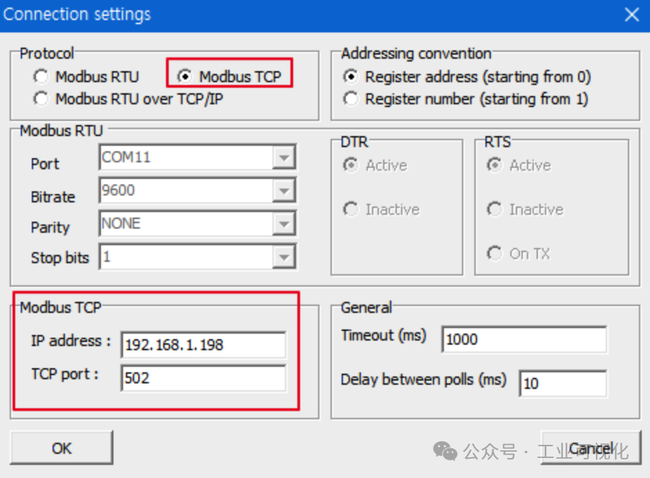
4.Stop Bits
Stop Bits indicate a fixed interval signal after data transmission, marking the end of a data frame. Common settings are 1 or 2 bits:
-
1 Stop Bit (common setting): Suitable for transmitting uncompressed data or in stable flow scenarios.
-
2 Stop Bits: Suitable for environments with high noise interference, providing stronger fault tolerance.
-
Configuration Requirement: Stop bits must match the communication partner; mismatches will lead to communication failure.
Setting Example:
StopBits = 1
5.Slave ID
Each Modbus slave device has a unique identifier called theSlave ID, ranging from 1 to 247, used by the master to distinguish between different devices.
- Configuration Requirement: The address must be unique. Duplicate addresses will cause commands sent by the master to be assigned to multiple devices, resulting in data conflicts.
- Practical Advice:
- Plan the address distribution in the system to avoid address conflicts when expanding devices later.
- Use tools to uniformly check the addresses of all connected devices.
Setting Example:
SlaveID = 35
6.Timeout
Timeout refers to the maximum time the master device waits for a response from the slave device, usually measured in milliseconds (ms).
- Configuration Requirement: The timeout cannot be too long or too short, as it may disrupt communication efficiency.
- Practical Advice:
- When network performance is good, set the timeout between 100-500ms;
- In cases of low transmission quality or limited device processing capability, appropriately extend the time to 1000-3000ms.
Setting Example:
Timeout = 1000ms
7.Communication Mode: RTU or ASCII

Modbus supports two communication modes:
- RTU Mode: Sends data in hexadecimal, high efficiency but difficult for manual interpretation.
- ASCII Mode: Transmits in character format, easy for manual reading but lower efficiency.
The choice between the two depends on the application scenario:
- For machine-to-machine communication, RTU mode is almost always preferred.
- When manual intervention or debugging is needed, ASCII mode can be chosen.
Setting Example (Recommended RTU):
Mode = RTU
Properly setting Modbus communication parameters is essential for achieving efficient and stable communication between devices. Parameters such as baud rate, data bits, parity, and stop bits should be flexibly adjusted according to the application scenario, while slave addresses and timeout settings need to be uniformly planned and tested. While standardizing these parameters, adjustments should also be made based on the actual operating environment to significantly improve communication stability.
Recent Hot Articles:
| Domestic host computer development framework, efficiency +200%! yydsSwitching to WPF for host computer development is really better???yyds! An open-source MES written in C#, amazing!yyds! Modbus master station tool made with QtHow to implement scheduled tasks in host computer development?Domestic MES! Work order → process fully covered! yyds |