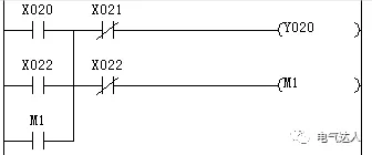
For engineers who have been exposed to PLC programming, concepts such as self-locking, interlocking, and mutual locking are certainly familiar. These are typical foundational elements in PLC programming and are core skills that must be mastered. Next, we will introduce several classic small program examples.
1. Self-Locking (Start-Stop Control)
The PLC control circuit for self-locking (start-stop control) consists of a start signal (normally open contact), a stop signal (normally closed contact), an output coil, and a normally open auxiliary contact of the coil. The working sequence is as follows: the start signal triggers → the coil is energized, the auxiliary contact closes → after the start signal disappears, the closed auxiliary contact maintains the coil energized → until the stop signal cuts off the circuit. Compared to jog control, it achieves continuous operation through self-holding characteristics with a single trigger, widely used in continuous control of devices such as motors.
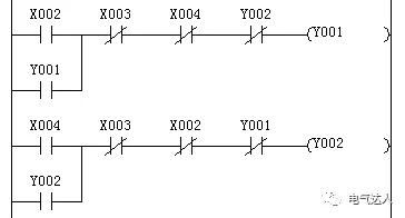
 2. Interlocking and Mutual Locking (Forward and Reverse Rotation)
Interlocking control is formed by connecting multiple input contacts in series to create an “AND” logic, activating the output only when all conditions are met; mutual locking, on the other hand, uses normally closed contacts of output states to implement mutual constraints between multiple outputs, preventing conflicting actions (such as prohibiting simultaneous operation of motors in forward and reverse).
 3. Flashing Circuit (Alarm Light)
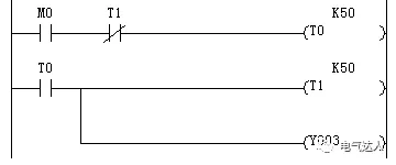
The flashing circuit (or oscillating circuit) is implemented through two timers (on-delay and off-delay) working alternately to achieve PLC control logic, used to drive output devices (such as indicator lights) to complete the on-off cycle switching. Its working principle is: after the on-delay timer times out, it triggers the output to turn off and starts the off-delay timer; after the latter times out, the output is re-energized and the previous timer is reset, forming a loop. By setting the preset values of the two timers (e.g., on for 1 second, off for 0.5 seconds), the total cycle (1.5 seconds) and flashing frequency (approximately 0.67Hz) can be controlled. It is typically applied in scenarios requiring visual alerts, such as fault alarm indicator lights.
 4. Delayed On and Delayed Off
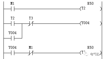
Timers can achieve two types of delay control: one is to close the output after a specified delay, and the other is to open the output after a specified delay.
 5. Alternating Output (Single Button Control Start-Stop)
The alternating output circuit is a single button start-stop control, and its programming methods are diverse; this article will only introduce one typical scheme.
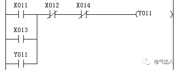
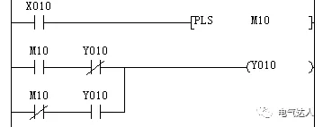 6. Multi-Point Start-Stop
When controlling the same output from multiple locations, normally open contacts need to be connected in parallel, and normally closed contacts in series to achieve multi-point start-stop control.
 7. Jogging Plus Interlocking Operation
In electrical control, the jogging function is realized in relay systems through the mechanical characteristics of composite buttons that first disconnect and then connect. When converted to a ladder diagram, the jogging and interlocking functions can be integrated through optimized control circuits. The key logic is: when X22 is disconnected, the M1 coil is delayed to de-energize, and its normally closed contact cuts off the self-locking circuit of Y22, thus achieving jogging control.