This article is an excellent piece from the KX forum, authored by KX forum user ID: blck四
In my usual research on binary vulnerabilities and kernel issues, I have found answers on KX, and I am very grateful to these predecessors for sharing their problem-solving ideas, which helps future generations avoid pitfalls.
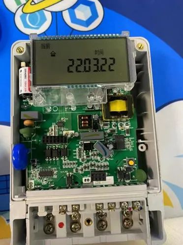
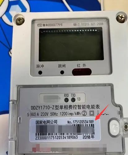
Device Information and Structural Composition
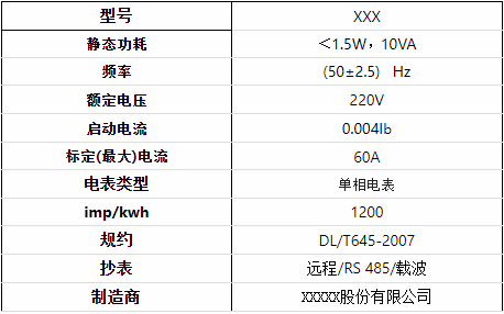
Parameter Information:
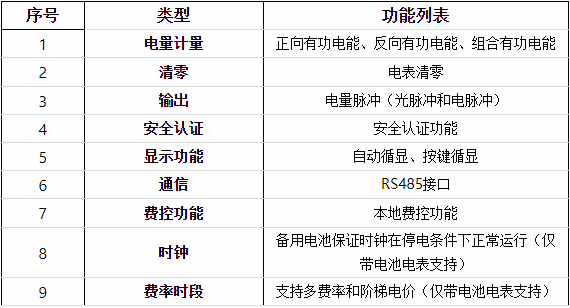
Functional Configuration:
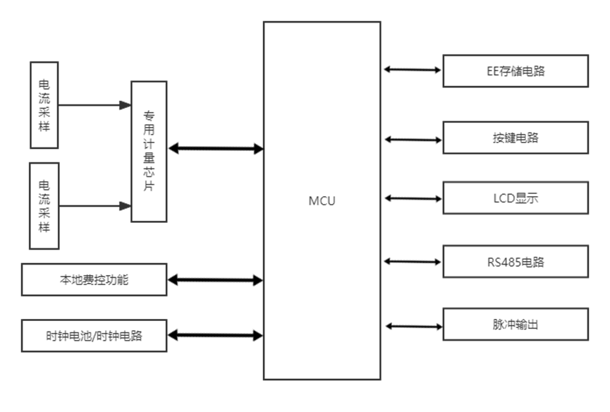
Structural Composition:
Communication Methods
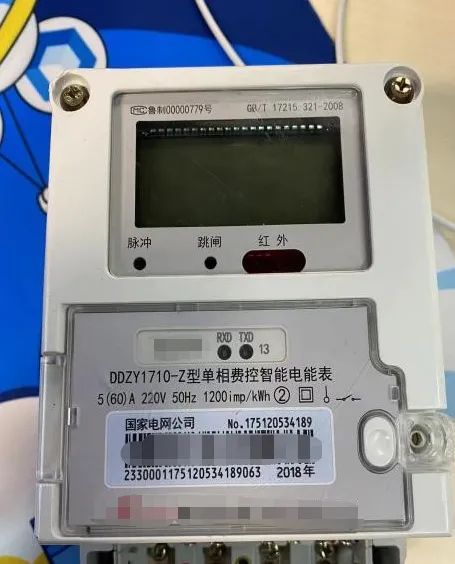
From the detailed parameters of the meter, it can be seen that the main supported communication methods are pulse communication and carrier communication. This meter supports establishing communication connections using the RS485 protocol, which is a type of serial port. Common types include RS232 and RS422, all of which belong to serial ports. RS485 is half-duplex communication, with a transmission rate of about 10Mbps. When sending data, the control CTRL is at a high level, and data is sent through TXD (located at the bottom right of the meter diagram). To receive data, the control CTRL is at a low level, and data is received back through RXD (located at the second position at the bottom right of the meter diagram), achieving send and receive. In simple terms, it converts the TTL signal that swings between “0-3.3V/5V” into a “5V differential inverted AB line signal”.
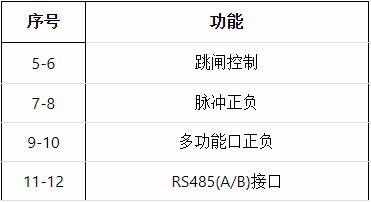
The leftmost numbers starting from 5 to 12 represent the external interfaces, each corresponding to the PCB.
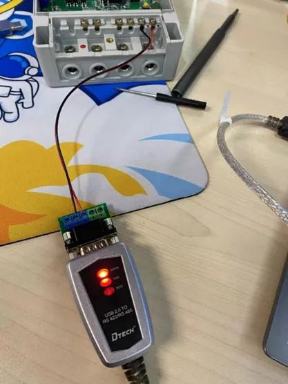
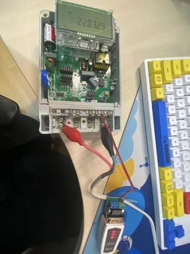
I used an RS485 subline to connect A/B for asynchronous serial communication, as shown in the following diagram. Positive to positive, negative to negative (data+ data-).
If there is abnormal communication, you can determine whether the problem lies in the adapter (I encountered an adapter failure during actual experiments and found the problem through short-circuit testing, eventually buying a new adapter). The converter subline should connect positive to positive and negative to negative for short-circuit testing.
Check the system device manager to see if any COM ports are connected. If so, serial communication can be established. The baud rate can generally be set to either 2400 or 9600, with the parity bit changed to “even parity”.
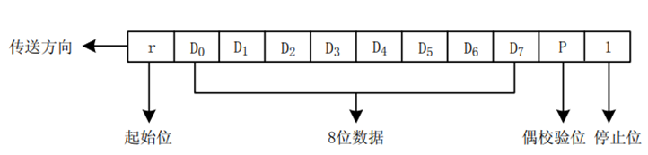
The byte format of the baud rate consists of 8 bits of binary code per byte, with one start bit (0), one even parity bit, and one stop bit (1), totaling 11 bits. As shown in the diagram, D0 is the least significant bit of the byte, and D7 is the most significant bit. Low bits are sent first, followed by high bits.
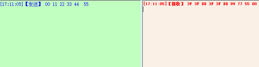
Try sending data to see if it can be received normally. Since this is a short-circuit test, whatever data is sent will be received.
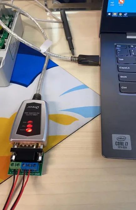
If no data is received, there may be an issue with your conversion interface or subline connection. After completing the above tests, power can be supplied to the meter. First, connect one end of the adapter to the computer USB, then connect the subline to the meter’s RS485 A/B port, remembering: positive to positive, negative to negative.
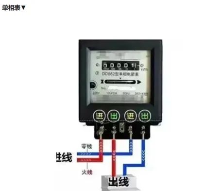
This model is a single-phase energy meter, with four terminals from left to right numbered 1, 2, 3, 4. The analysis diagram of the single-phase meter shows the fire and neutral wires (1 and 3 are input, 2 and 4 are output, 1 is fire and 3 is neutral).
Here, I made a simple wire myself, using ports 1 and 4 to form a circuit (1 can connect to 3 or 4, but do not connect to port 2; connecting fire to fire will cause a trip).
After plugging into the socket, you can open the serial port and communicate with the meter via USB.
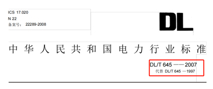
The meter has a dedicated power communication standard, which is a national standard collectively known as 645 “DL/T 645”. The communication standard was first released in 1997 as “DL/T 645-1997”, and then updated in 2007 to “DL/T 645-2007”, which has now replaced the 1997 standard, as can be seen from the information header.
The power protocol is relatively complex, and it takes about half a month to a month to fully understand the standard.
Reading Meter Data
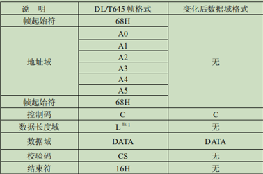
Currently, the mainstream new meters are still version 07. Below, I will analyze the communication protocols of these two types of meters:
The standard mentions that the protocol uses a master/slave structure for half-duplex communication. Each frame consists of eight fields: preamble, frame length, feature field, address field, control field, data field, checksum field, and end flag.
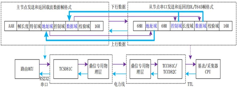
According to this standard format, the meter data can be read. In practical application scenarios, the downlink and uplink data transmission formats between the master node and the base meter MCU are as follows:
Relay routing situations may also occur, and there may be other complex scenarios. A code for reading and writing data via serial port has been implemented here using C/C++.
First, try to read the meter’s address. According to the standard, if the address of the meter is unknown, AAH can be used as a substitute address.
Send data: 68H AAH AAH AAH AAH AAH AAH 68H 13H 00H DFH 16H
Since I spent little time writing the code, I haven’t included the synchronous code for the serial port, but it doesn’t matter. According to the standard, 16H is the end flag. (The code is not well formatted, so I won’t post it)
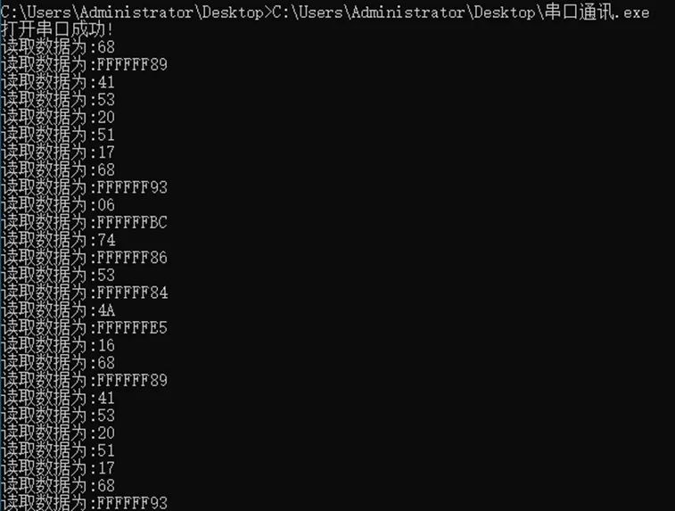
The organized data is: 68 89 41 53 20 51 17 68 93 06 BC 74 86 53 84 4A E5 16
Thus, I successfully obtained the returned data from the meter. Through standard parsing:
894153205117 (address field)
BC 74 86 53 (data field register address)
E5 16 (checksum/end flag)
According to the transmission order – low first, high later, the meter’s address is obtained as 175120534189. Later I found that this address corresponds to the string No. on the casing label.
The calculation formula for the meter number: data item – 33H = meter number
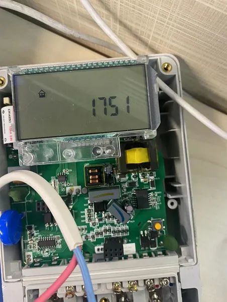
The meter number is: 1751
It is also possible to obtain data such as power consumption data, meter time, peak and valley values, total electricity consumption, amount, etc.
KX ID: blck四
https://bbs.pediy.com/user-home-748627.htm
*This article is original by KX forum blck四, please indicate the source from KX community if reprinted
# Previous Recommendations
1.[VNCTF2022] gocalc0 Reproduction
2.CVE-2018-8120 Privilege Escalation Vulnerability Study Notes
3.IDA Automatic Structure Analysis Plugin Based on LLVM Compiler
4.2022 CTF babyarm Kernel Problem Detailed Analysis
5.Go Parsing
6.IoT Device Obtaining Local Shell Access and Software Debugging