Learning Microcontroller Development from Basics to Advanced: Using Timers (Part 3) – PWM Output Function
This article explains the function and configuration method of the timer PWM mode.
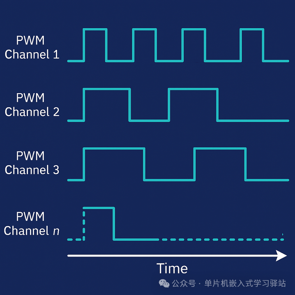
In microcontroller applications, the PWM output mode of timers is an efficient and commonly used function, widely applied in power electronic control systems, LED dimming, audio signal generation, motor control, and other scenarios. The powerful timer module of the STM32 series microcontrollers provides flexible PWM output capabilities.
PWM Principles and Application Scenarios
PWM Principles
PWM (Pulse Width Modulation) signals are periodic signals that achieve equivalent DC voltage by changing the duration of the high level. The higher the duty cycle, the higher the corresponding average voltage, as follows:
- • 50% duty cycle: equivalent to half of the high-level voltage;
- • 100% duty cycle: equal to the high-level voltage;
- • 0% duty cycle: equal to the low-level voltage;
Therefore, if the duty cycle can be flexibly controlled between 0% and 100%, it is possible to dynamically change the voltage level.
Application Scenarios
PWM signals are commonly used in power system control, LED dimming, motor control, etc. For example, in LED dimming applications, as shown in the schematic diagram below:
LED Dimming Control
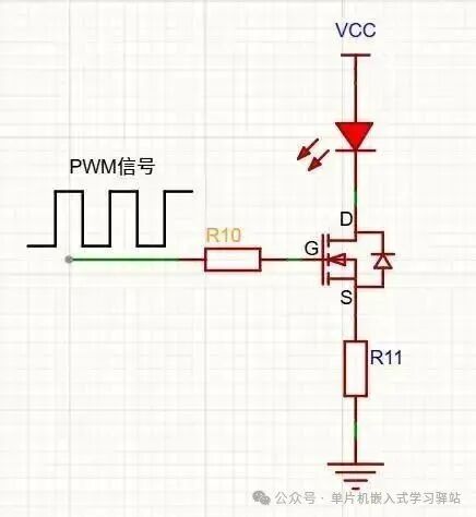
If the PWM signal varies from 0% to 100% duty cycle, the LED will exhibit a fading effect. The above diagram is a simple LED dimming control. To achieve smooth and accurate brightness changes, a constant current is required, and the PWM controls the current level to create the fading effect of the LED.
DC Motor Control
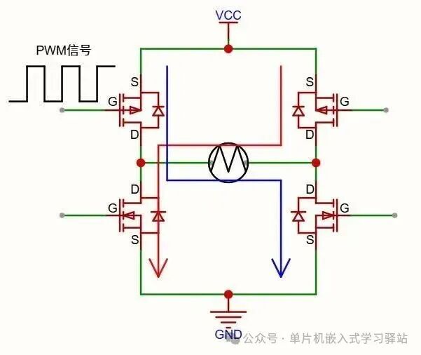
DC motor control generally uses an H-bridge circuit, as shown in the diagram below. By applying PWM signals to the bridge arms, motor speed control is achieved. (A separate article will be written on motor control, which is not covered in this article.)
STM32 Microcontroller Timer PWM Output Mode
PWM Output Frequency Calculation
The output frequency of the timer is calculated from the <span>ARR reload register value</span> and the <span>PSC input clock prescaler</span>:
Calculation method:
Where:
- • Fclk: Timer input clock frequency;
- • Vpsc: Value of the prescaler register;
- • Varr: Value of the auto-reload register;
Related Structures (Using Register Library Functions)
Time Base Configuration Structure:<span>LL_TIM_InitTypeDef</span>
typedef struct
{
  uint16_t Prescaler;         // Prescaler value for counting clock
  uint32_t CounterMode;       // Counting direction
  uint32_t Autoreload;        // Auto-reload count value
  uint32_t ClockDivision;
  uint32_t RepetitionCounter;
} LL_TIM_InitTypeDef;
The meaning of this structure’s parameters has been introduced in the previous article, so it will not be repeated here.
Output Configuration Structure<span>LL_TIM_OC_InitTypeDef</span>
This structure works with the function <span>LL_TIM_OC_Init</span> to complete the timer output mode configuration.
typedef struct
{
  uint32_t OCMode; // Output mode selection, PWM mode is PWM_MODE_1 or PWM_MODE_2
  uint32_t OCState; // Whether to enable output
  uint32_t OCNState; // Complementary channel output valid state, applicable only to advanced timers
  uint32_t CompareValue; // Comparison value, determines duty cycle
  uint32_t OCPolarity; // Output signal polarity selection
  uint32_t OCNPolarity; // Complementary channel output signal polarity selection, applicable only to advanced timers
  uint32_t OCIdleState; // Level when output is idle (dead time or emergency stop), applicable only to advanced timers
  uint32_t OCNIdleState; // Level when complementary channel is idle, applicable only to advanced timers
} LL_TIM_OC_InitTypeDef;
The configuration process for output comparison is described in the reference manual as follows:
- 1. Select the timer counting clock source;
- 2. Write the count reload value ARR and capture compare value CCR according to the required output frequency and duty cycle;
- 3. If necessary, set the timer interrupt enable bit or DMA request enable bit (optional);
- 4. Set the
<span>CCMR register</span>to select the output mode; - 5. Finally, set the
<span>CR register</span>to enable the timer;
For general timers, only the four parameters <span>OCMode</span>, <span>OCState</span>, <span>CompareValue</span>, and <span>OCPolarity</span> need to be set;
Here, we will focus on the relationship between <span>OCxREF</span> and <span>OCx</span> in the STM32 microcontroller timer output structure;
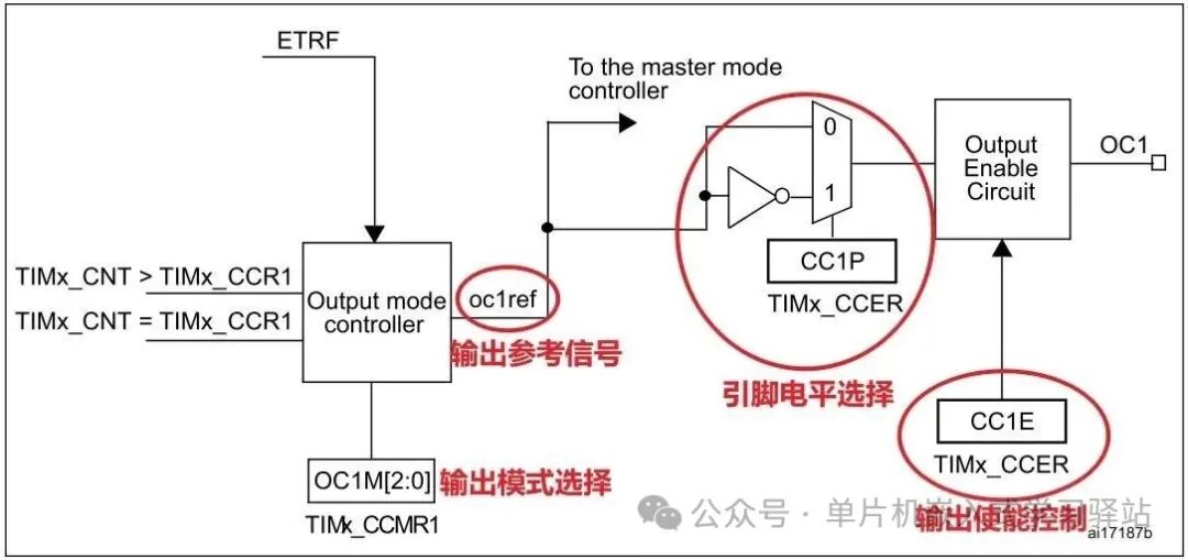
In the reference manual, all comparison output results are explained using the <span>OCxREF</span> reference signal, but the signal output to the pin is actually <span>OCx</span>. So what is the actual correspondence between these two signals? Here is a brief explanation:
Taking PWM Output Mode 1 as an example, when configured in up-counting mode, if <span>CNT < CCR</span>, then <span>OCxREF</span> is valid; if <span>CNT >= CCR</span>, then <span>OCxREF</span> is invalid; this does not mean that when it is below <span>CCR</span>, the pin is high. Changing the value of <span>CCR</span> can control the PWM high-level duty cycle, but it must also be combined with a parameter to determine the actual output level;
STM32 microcontroller specifies:
<span>OCxREF=1 (high level), valid state; OCxREF=0 (low level), invalid state</span>;
The actual output pin level must also be combined with the configuration parameter <span>OCOolarity output polarity</span> to determine. This configuration corresponds to the <span>TIMx_CCER</span> register’s <span>CCxP</span> bit, which, together with the <span>OCxREF</span> signal, determines the actual output level of <span>OCx</span>. The relationship among the three is shown in the table below:
| OCxREF | Polarity (Polarity Selection) | OCx (Output Pin Level) |
|---|---|---|
| 0 (Invalid) | 0 | 0 (Low Level) |
| 0 (Invalid) | 1 | 1 (High Level) |
| 1 (Valid) | 0 | 1 (High Level) |
| 1 (Valid) | 1 | 0 (Low Level) |
According to the above table, when <span>CCxP=0</span>, the output level matches <span>OCxREF</span>; when <span>CCxP=1</span>, the output level is opposite to <span>OCxREF</span>.
Therefore, when configuring the PWM mode, if you want the actual output signal to match the expected one, it is essential to understand the relationship among these three; otherwise, unexpected effects may occur, leading to suspicions of hardware or software issues.
Test Code: Breathing Light
The test code uses timer compare interrupts to dynamically change the duty cycle by updating the compare register value: the duty cycle values are pre-generated and stored in an array, and when the compare interrupt occurs, the compare register value is updated in the interrupt handler.
Code Writing
Generating Breathing Light Duty Cycle Array
void breath_waveform_gen(uint16_t* const parray,float sample_rate, float freq, uint16_t amp)
{
    int dot_nums = sample_rate/freq; // Number of sample points in one cycle
    float t=0;
    amp >>= 1;
    for(int i=0; i<dot_nums; (1.0f="" (cosf(2.0f="" *="" *(parray="" +="" -="" 3.1415926f="" code="" freq="" i)="amp" i++)="" t="((float)i)/sample_rate;" t)));="" {="" }="" }
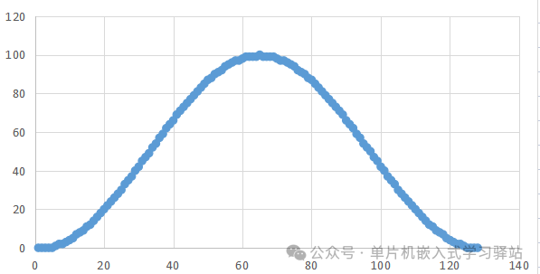
Generated signal graph:
Timer PWM Mode Configuration
uint16_t tim_pwm_mode_cfg(TIM_TypeDef* pTim, uint16_t freq, uint32_t channel)
{
    if(pTim == TIM3)
    {
        __HAL_RCC_GPIOB_CLK_ENABLE();
        __HAL_RCC_TIM3_CLK_ENABLE();
        LL_GPIO_InitTypeDef cIO;
        cIO.Mode           = LL_GPIO_MODE_ALTERNATE;
        cIO.Pin            = LL_GPIO_PIN_0;
        cIO.OutputType     = LL_GPIO_OUTPUT_PUSHPULL;
        cIO.Speed          = LL_GPIO_SPEED_FREQ_HIGH;
        LL_GPIO_Init(GPIOB, &cIO);
    }

    LL_TIM_InitTypeDef cTimBase;
    LL_TIM_StructInit(&cTimBase);

    uint32_t Fclk = SystemCoreClock;
    if (!IS_TIM_BREAK_INSTANCE(pTim))
    {
        Fclk >>= 1u; // Fclk/2, non-advanced timer clock input speed is half of the system clock
    }

    cTimBase.Prescaler         = Fclk/1000000U - 1U; // First, divide the input clock to 1MHz
    cTimBase.Autoreload        = 1000000U/freq - 1;  // Then calculate the prescaler value for 1MHz clock at the target frequency
    cTimBase.RepetitionCounter = 0;
    cTimBase.ClockDivision     = LL_TIM_CLOCKDIVISION_DIV1;
    LL_TIM_Init(pTim, &cTimBase); // Call time base configuration function

    LL_TIM_OC_InitTypeDef cTimOC;
    LL_TIM_OC_StructInit(&cTimOC);
    cTimOC.OCMode        = LL_TIM_OCMODE_PWM1; // Select PWM mode 1
    cTimOC.OCState       = LL_TIM_OCSTATE_ENABLE; // Enable output
    cTimOC.OCPolarity    = LL_TIM_OCPOLARITY_HIGH; // Active high
    cTimOC.CompareValue  = 0; // Duty cycle
    LL_TIM_OC_Init(pTim, LL_TIM_CHANNEL_CH3, &cTimOC); // Call output mode configuration function
    LL_TIM_OC_EnablePreload(pTim, LL_TIM_CHANNEL_CH3); // Enable preload, CCR register will only update after an update event;
    LL_TIM_GenerateEvent_UPDATE(pTim); // After enabling OC preload, an update event must be triggered to initialize the register
    return cTimBase.Autoreload;
}
Interrupt Handler Function
void TIM3_IRQHandler(void)
{
    static uint16_t i=0;
    uint16_t sr = TIM3->SR; // Read status register to get interrupt event
    if(sr & LL_TIM_SR_CC3IF)
    {
        TIM3->CCR3 = wave[i]; // Update compare register value
        LOG_INFO("duty update[%d] at:%d\n", wave[i], HAL_GetTick());
        if(++i >= 256)i=0;
        LL_TIM_ClearFlag_CC3(TIM3); // Clear interrupt flag
    }
    HAL_NVIC_ClearPendingIRQ(TIM3_IRQn); // Clear pending interrupt flag in interrupt controller
}
Call Configuration Function to Initialize Timer in Main Function
Configuration process:
Configure timer PWM mode
Generate breathing waveform
Enable timer compare interrupt
Configure interrupt controller to enable timer interrupt
Start timer
The code in the main function sets the signal frequency to <span>1Hz</span><span>, sampling frequency to 256Hz, and output frequency to 128Hz:</span>
uint16_t amp = tim_pwm_mode_cfg(TIM3,128,LL_TIM_CHANNEL_CH3); // Configure PWM mode: output frequency 128Hz
breath_waveform_gen(wave,256.0f,1.0f,amp); // Generate breathing light duty cycle waveform data, sampling frequency 256Hz, signal frequency 1Hz
LL_TIM_EnableIT_CC3(TIM3); // Enable compare interrupt
HAL_NVIC_SetPriority(TIM3_IRQn, 0, 0); // Configure timer 3 interrupt priority
HAL_NVIC_EnableIRQ(TIM3_IRQn); // Enable timer 3 interrupt
LL_TIM_EnableCounter(TIM3); // Start timer
Test Results
Conclusion
When first learning to use a peripheral, it is necessary to refer to the chip reference manual for specific function descriptions and register details. Simply looking at the comments in the library functions does not provide insight into the details of peripheral usage. At the same time, key positions should still directly manipulate registers to improve efficiency and reduce code size.
This concludes the content of this article. Thank you for reading;
Click here to view other articles from the public account: