1. Introduction
It is common to encounter questions about how to place the capacitors for FPGA and how many to use. Generally, this is based on the development board or reference circuits, without in-depth consideration.
2. Design Principles
This article estimates the size and quantity of power filtering capacitors based on the target impedance method.
3. Detailed Analysis
The main factors affecting the filtering effect of capacitors are parasitic inductance and capacitance. The filtering capacitor communicates with the parasitic inductance to form an LC circuit, which behaves capacitively below the resonant frequency and inductively above it.
The lower the internal resistance of the power supply, the stronger the current capability it provides externally. When designing, selecting appropriate capacitors and quantities can ensure that the internal resistance of the power supply meets the chip power voltage fluctuation specifications under specified dynamic current conditions.
Zmax=VPP/X
VPP is the fluctuation range required for the power supply voltage, determined by the device operating voltage and the precision of the power supply voltage.
The instantaneous current required by the load is generally taken as 0.1-0.9 times the dynamic current based on power consumption.
Taking the core voltage as an example, the supply voltage is 0.9+ —-4%. The maximum current is 0.883A.
Based on this, we calculate the target impedance to be approximately 0.08 ohms.
Selection of Low-Frequency Capacitors
The DCDC power supply frequency has segmented characteristics. For low-frequency bands, DCDC directly supplies power, while for high-frequency bands, capacitors primarily provide power. Taking the typical 1MHz DCDC power switch frequency as an example, we use 0.1 times as the boundary for the switching frequency. For signals from 0-100K, the switching power supply is regarded as an ideal power source, while for signals above 100K, the power is supplied by capacitors.
Based on the capacitive reactance and the previously calculated target impedance, we can calculate the required capacitance value and then select the appropriate capacitor from the capacitor library.
Selection of High-Frequency Capacitors
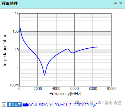
The impedance frequency curve of capacitors shows that when the frequency is in the hundreds of MHz, the capacitors exhibit inductive reactance, which can only be reduced by parallel connection.
Using the same method to calculate small capacitance capacitors, the inductance is calculated based on the cutoff frequency of high-frequency capacitors at 200M, ensuring compliance.
In the range of 100KHZ to 200MHZ, to ensure the current resource utilization, the required capacitor configuration can meet the power supply ripple requirements as shown in the table below. When placing on the PCB, the capacitor’s tolerance should also be considered, and it can be expanded by 3-5 times based on actual conditions to ensure sufficient margin. Additional capacitors of other values can be added to further smooth the actual impedance curve of the power supply. If magnetic beads are introduced into the circuit during the design process, the parasitic inductance introduced by the magnetic beads must also be considered. Therefore, the design of power filtering capacitors is a comprehensive consideration, constrained by multiple factors. However, the evaluation method remains the same, ensuring that the power supply circuit has sufficient energy supply based on the frequency characteristics of the capacitors.