IO-Link to Modbus TCP – ADFWEB Gateway Converter– Guangzhou Xinyu IoT
Author:www.adfweb.com.cn Zou Wuyi Mobile185-020-77899 Email: [email protected]
1、Features:
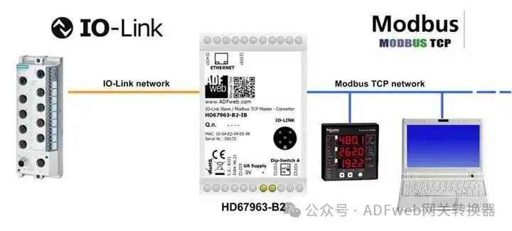
HD67963-B2 is an IO-Link slave/Modbus TCP master converter, with the following functions:
– Maximum read/write data volume can reach 1500 bytes;
– Can be installed on 35mm DIN rail;
– Supports Modbus TCP and IO-Link bidirectional data transmission;
– Class A or Class B versions can be selected based on the order code;
– Wide temperature operating range:-40°C to 85°C (-40°F to +185°F).
Configuration:
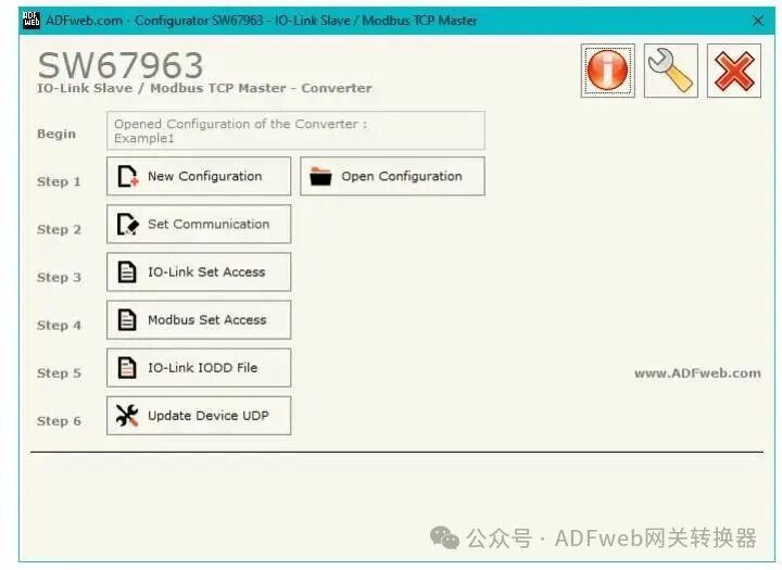
It is necessary to install Compositor SW67963 software on a PC to perform the following operations:
– Define IO-Link line parameters;
– Define Modbus TCP line parameters;
– Set the process data and parameters for the converter’s IO-Link port;
– Formulate Modbus read/write request list;
– Generate IODD (Information Description Document) file for IO-Link master;
– Update device firmware.
2、**New Configuration/Open Configuration:**
The “New Configuration” button is used to create a folder containing the entire device configuration.
The device configuration can also be imported or exported:
– To clone the programmable “IO-Link slave/Modbus TCP master converter” configuration to configure another device in the same way, the folder and all its contents must be retained;
– To clone the project for different versions, simply rename the project folder to another name and use the “Open Configuration” button to open the new folder.
3、Setting Communication:
This section defines the basic communication parameters for the two buses (IO-Link andModbus TCP).
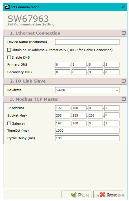
By clicking the “Set Communication” button in the SW67963 main window (Figure 2), the “Set Communication” window (Figure 3) will appear.
The settings for the “Ethernet Connection” related fields are as follows:
– In the “Device Name (Hostname)” field, define the hostname to be assigned to the converter;
– If the “Automatically Obtain IP Address (Wired Connection Using DHCP)” option is selected, enable DHCP functionality for the LAN connection;
– If the “Enable DNS” option is selected, enable DNS protocol;
– In the “Primary DNS” field, define the IP address of the primary DNS server;
– In the “Secondary DNS” field, define the IP address of the secondary DNS server.
“IO-Link Slave” related fields are set as follows:
– In the “Baud Rate” field, define the standard baud rate used by the IO-Link interface.
“Modbus TCP Master” related fields are set as follows:
– In the “IP Address” field, define the IP address of the converter’s Modbus TCP end;
– In the “Subnet Mask” field, define the subnet mask of the converter’s Modbus TCP end;
– In the “Gateway” field, define the default gateway for the network. This function can be enabled or disabled using a checkbox for leaving the network;
– In the “Timeout (ms)” field, define the maximum time the converter waits for a response from the queried slave;
– In the “Cycle Delay (ms)” field, define the delay time between two Modbus requests (idle time).
4、IO-Link Setting Access:
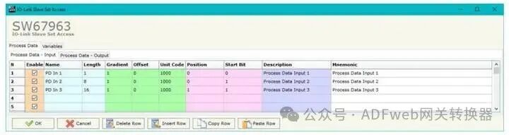
By clicking the “IO-Link Setting Access” button from the main window of SW67963 (Figure 2), the “IO-Link Slave Setting Access” window (Figure 4) will pop up.
This section is used to define the data read/write from the Modbus TCP slave and its corresponding variables.
Process Data
The meanings of the fields are as follows:
– If the “Enable” field is checked, the IO-Link variable will be enabled;
– In the “Name” field, define the name of the IO-Link variable;
– In the “Length” field, define the number of bits for the variable;
– In the “Gradient” field, define the rate of change for the variable;
– In the “Offset” field, define the offset value for the variable;
– In the “Unit Code” field, define the unit for the variable;
– In the “Position” field, define the starting byte of the internal memory array used to store data;
– In the “Starting Bit” field, define the starting position for data mapping;
– In the “Description” field, define the description of the variable;
– In the “Mnemonic” field, remarks can be added.
5、MODBUS Setting Access:
By clicking the “Modbus Setting Access” button in the SW67963 main window (Figure 2), the “Set Modbus TCP Host Access” window will appear.
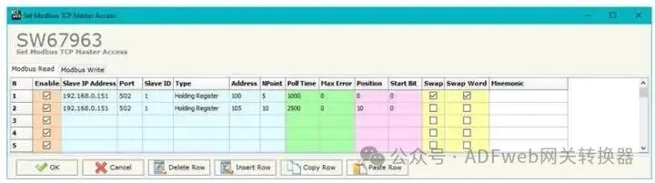
This window is divided into two parts: “Modbus Read” (Figure 5a) and “Modbus Write” (Figure 5b).
The first part “Modbus Read” is used to read data from the Modbus slave device and make it available on the IO-Link side.
The second part “Modbus Write” is used to write data from the IO-Link side to the Modbus slave device.
**Modbus Read**
The meanings of the fields are as follows:
– If the “Enable” field is checked, enable the Modbus request;
– In the “Slave Device IP Address” field, define the IP address of the Modbus TCP device to be read;
– In the “Port” field, define the TCP port used for communication;
– In the “Slave Device ID” field, define the address of the Modbus TCP device to be read;