What is GTH
GTH is a type of high-speed transceiver on Xilinx UltraScale series FPGAs. It is essentially similar to other types such as GTP and GTX, differing only in device type and speed; GTH has a minimum speed of 500 Mbps and a maximum speed of 16 Gbps.
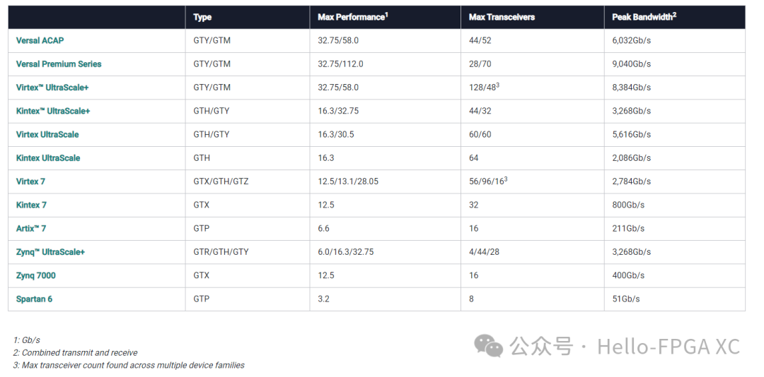
Both CoaXpress Host and Device IP require the vendor’s GT transceiver module, so this note is written as a development record.
Features of GTH
The physical coding sublayer (PCS) is the top layer of Xilinx high-speed transceivers.
The PCS (Physical Coding Sublayer) is a sublayer in the data link layer, located between the physical layer and the MAC (Media Access Control) layer. It is a component of the data link layer that implements the interface functions between the physical layer and the MAC layer.
The main tasks of the PCS layer are to convert the upper-layer data frames into signals that can be transmitted by the physical layer and to parse the received signals back into data frames. It primarily performs the following tasks:
Encoding and Decoding: The PCS layer is responsible for encoding the upper-layer data frames, converting them into signals that can be transmitted by the physical layer. This typically involves converting digital data into analog signals and encoding the signals at the sender’s end. The PCS layer at the receiver’s end is responsible for decoding the received signals back into digital data.
Clock Recovery: The PCS layer ensures accurate data transmission by performing clock recovery on the received signals. This includes identifying clock information in the received signal to correctly parse the data.
Transmission Encoding: The PCS layer may apply transmission encoding to enhance the reliability and efficiency of data transmission. This includes adding redundant check codes, error detection, and correction codes to improve the reliability of data transmission and ensure that errors do not occur during transmission.
Alignment: The PCS layer is responsible for aligning the received data to ensure that it can be correctly processed and parsed by the upper-layer MAC layer.
In summary, the PCS layer serves as an interface between the data link layer and the physical layer, responsible for encoding, clock recovery, transmission encoding, and alignment of upper-layer data to achieve reliable data transmission.
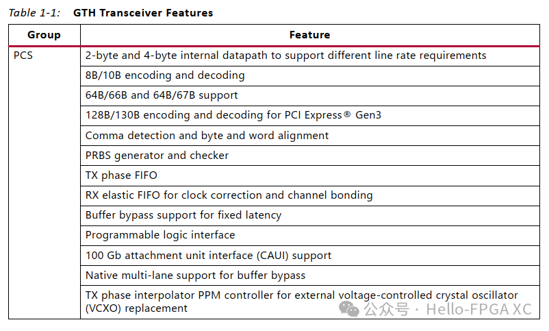
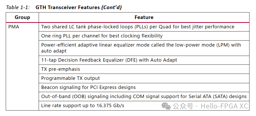
As can be seen, operations such as clock recovery, data encoding, and data alignment are all completed at the PCS layer. If CRC verification is needed, it can be implemented at a higher layer, calculating the CRC and transmitting the CRC result as normal data.
GTH Structure
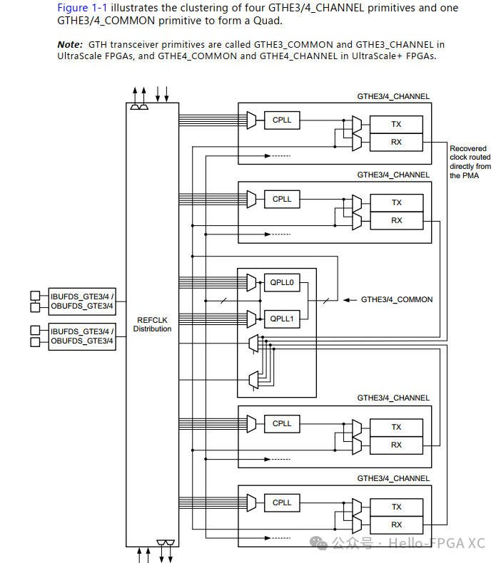
The following diagram shows the architecture of GTH, from which several pieces of information can be derived:
1. GTH is generally grouped in sets of 4, with 4 channels and 1 common clock section; the common section is responsible for the clock part, while the channel sections correspond to specific SERDES.
2. The clock recovery circuit is located in the PMA section.
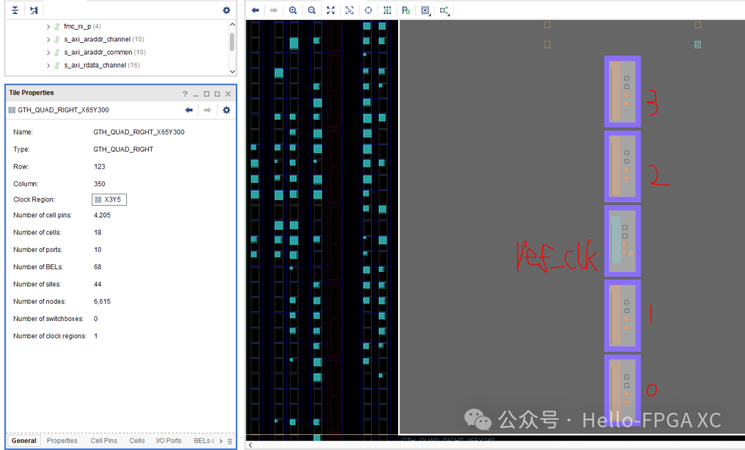
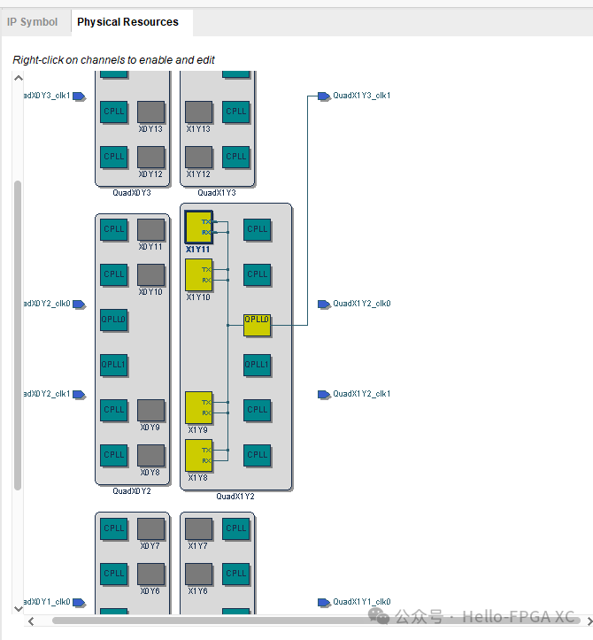
The parts that need attention during normal use are as follows:
8B/10B Encoding and Decoding, Taking RX as an Example
The GTH module has a built-in 8b/10b encoder/decoder.
For a single channel, the internal 40-bit width is typically selected, with a user mode of 32-bit width, as most protocols define user data as 1 word == 4 bytes.
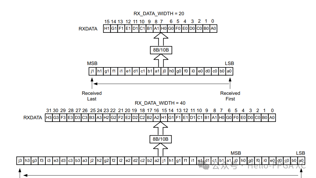
Error Indication of 8B/10B Encoding
The 8B/10B decoder performs out-of-table error detection and drives the RXCTRL3 port High when it is enabled,
but receives a 10-bit character that cannot be mapped into a valid 8B/10B character listed in Appendix A, Valid Data Characters. When this occurs, the
non-decoded 10-bit character is piped out of the decoder through the RX data interface with this format:
• The corresponding RXCTRL1 represents the 9th bit
• The corresponding RXCTRL0 represents the 8th bit
• The corresponding RXDATA byte represents the [7:0] bits
• The corresponding RXCTRL3 indicates that an invalid 8B/10B character error occurred
8B/10B Comma Alignment and Word Alignment
Alignment is done using K codes, with common K codes for alignment being K28.5 and K28.1. The following diagram uses K28.5 for alignment.
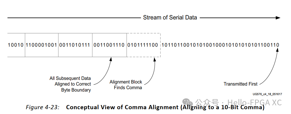
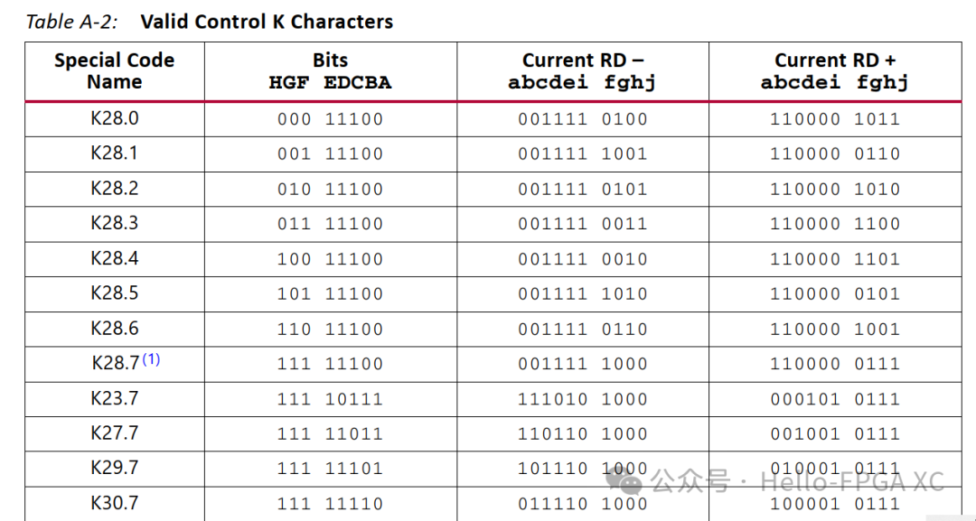
This only aligns bytes; how do we align words? For example, the high-speed transmission used in CoaXPress’s downconnection uses 1 word (4 bytes) as the minimum unit. How do we align words? GTH has already considered this, with the following configuration:
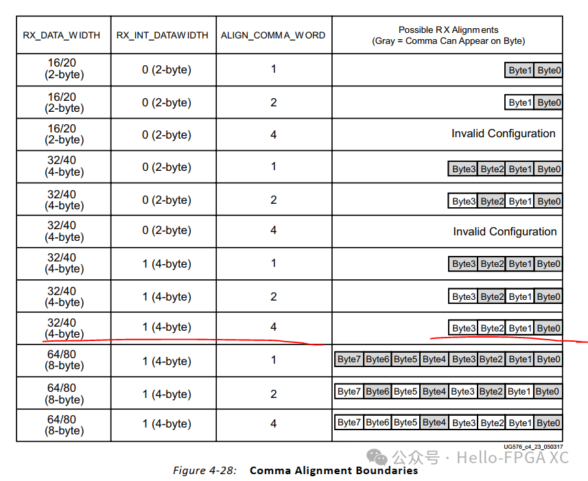
Corresponding to the GTWIZARD module, the configuration is as follows:
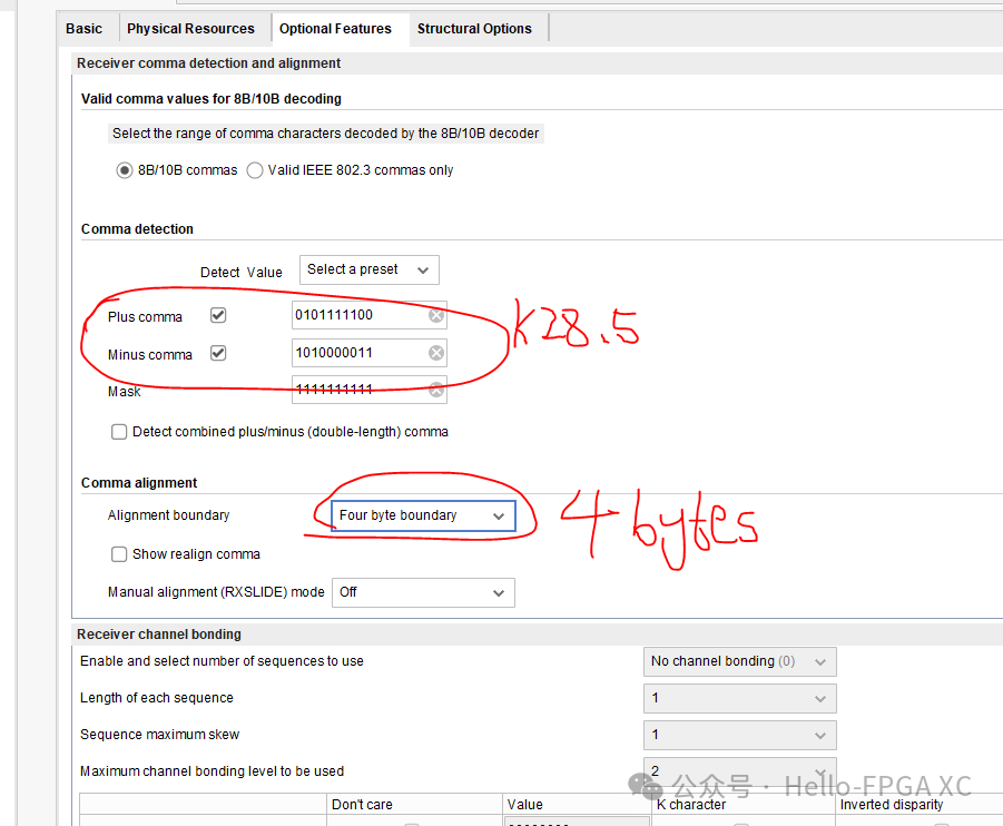
Based on the above configuration, the word data corresponding to the CoaXpress protocol can be correctly aligned and output.
(A word consists of 4 consecutive 8B/10B characters labeled P0, P1, P2, and P3 and are transmitted in the stated order (i.e., P0 first). The receiver shall perform word alignment in order to successfully decode the packets.)