Abstract: Virtual debugging technology is revolutionizing the execution of industrial automation projects. It connects PLC control programs with robot simulation models in a virtual environment, completing most debugging work before actual hardware deployment. This article will detail the process and key technical points of virtual debugging using mainstream simulation software in the industry as examples.
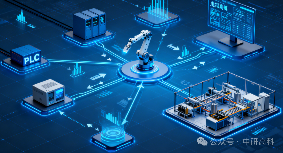
1. Core Value of Virtual Debugging
The core of virtual debugging lies in the “integration of virtual and real”. It allows engineers to begin verifying software logic, motion trajectories, and process cycles at an early stage of the project, even before mechanical processing is completed. This not only significantly shortens on-site debugging time and reduces rework costs due to design errors but also provides risk-free pre-training for operators.
2. Building a Virtual Debugging Environment
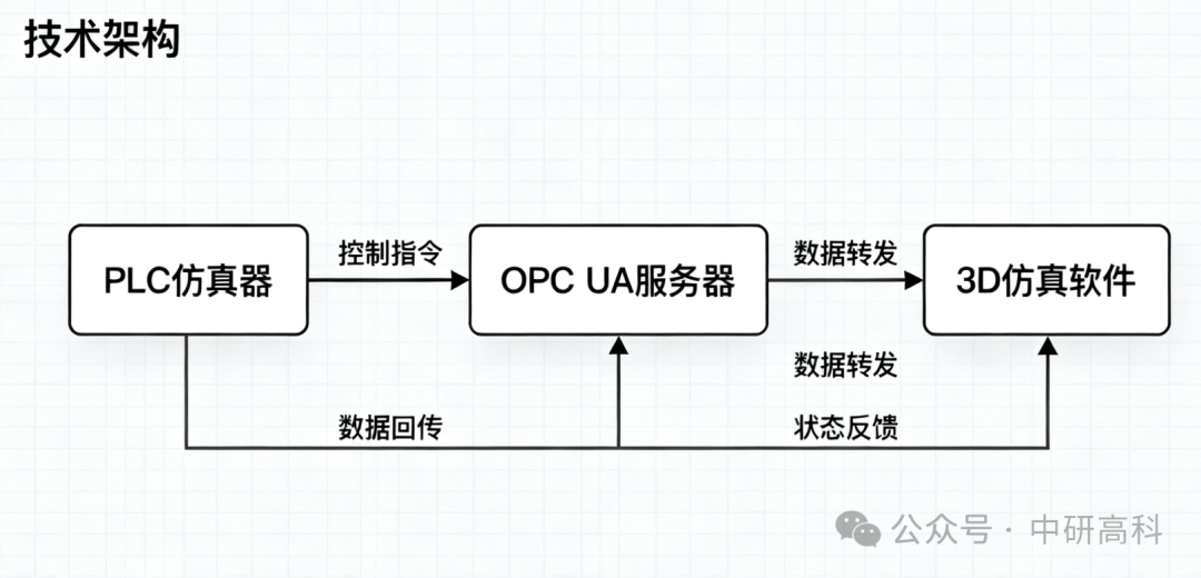
A typical virtual debugging environment consists of three core components:
-
Virtual Controller (PLC): Using virtualization software provided by PLC manufacturers (such as Siemens’ PLCSIM Advanced) or soft PLCs integrated within simulation software to run real control programs.
-
Robot Simulation Model: High-precision robot and work unit models constructed in professional robot simulation software (such as Visual Components, ABB RobotStudio, KUKA.Sim, Dassault’s 3DEXPERIENCE, etc.).
-
Communication Interface: The bridge connecting the first two components, typically using industrial communication protocols such as OPC UA, PROFINET, or TCP/IP.
3. Practical Connection of PLC and Robot Simulation
We will take Visual Components (VC) and Siemens S7-PLCSIM Advanced as examples to illustrate the connection steps:
Step 1: Configure the PLC Side Create a project in TIA Portal and write the control program for the robot (such as start, stop, target point selection, etc.). Configure the Ethernet parameters of the PLC and download it to run in PLCSIM Advanced, ensuring it is visible as “virtual hardware” on the network.
Step 2: Configure the Simulation Software Side In VC, define “signals” for the robot model. These signals need to correspond one-to-one with the I/O addresses in the PLC program. For example, define a boolean input signal <span>Robot_At_Home</span> and a boolean output signal <span>Start_Program_1</span>.
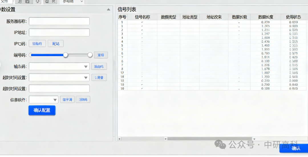
Step 3: Establish OPC UA Communication VC has a built-in OPC UA server function. In PLCSIM Advanced, use the OPC UA client function to connect to the server address provided by VC. Then, in VC’s signal mapping interface, bind the signals of the robot model to the OPC UA nodes.
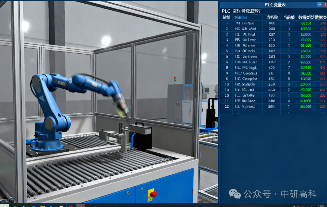
Step 4: Joint Debugging and Verification Start the entire system. At this point, force an output signal <span>Start_Program_1</span> to 1 in TIA Portal, and the robot in VC should immediately start executing the corresponding program. Meanwhile, when the robot reaches the Home position in VC, its <span>Robot_At_Home</span> signal should feedback to the PLC, making the corresponding input point become 1.
4. Key Considerations
-
Model Accuracy: The kinematics, dynamics, and geometric dimensions of the simulation model must be as accurate as possible; otherwise, the debugging results will lose their reference value.
-
Signal Synchronization: Ensure that the signal definitions between the PLC and the simulation software are completely consistent to avoid communication failures due to mismatched signal names or data types.
-
Clock Synchronization: The clocks of the virtual environment and the PLC should ideally remain synchronized to facilitate the analysis of timestamped logs and data.
Conclusion: Virtual debugging is one of the key technologies for achieving Industry 4.0 and digital twins. By seamlessly connecting PLCs with robot simulation models, companies can complete the development and verification of automation systems at lower costs, with higher efficiency and reduced risks.