
The standard configuration of Mitsubishi robots generally includes: the robot body, robot controller, and connection cables.
Note: The teach pendant is optional, meaning the standard configuration does not include a teach pendant. You can operate it in online mode using the officially provided software RT ToolBox3. Interested friends can download it from the Mitsubishi Automation official website.
Let’s take a look at the controller operation panel as shown in the figure below
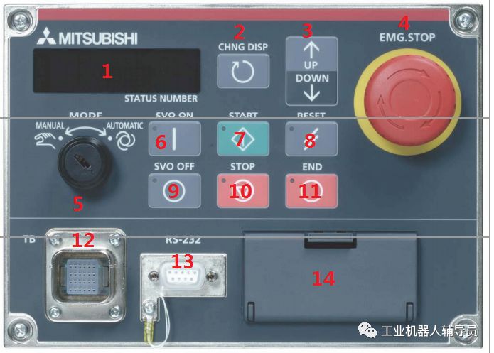
1. Status digital display screen
Displays the program error number, line number, speed, and other code number information showing its current status.
2. Switch between the status screens to view program numbers, line numbers, and speed status, allowing back-and-forth switching for display.
3. Up and down selections for program numbers and settings for speed increments and decrements.
4. Emergency stop button, used to disconnect the servo power during emergencies or maintenance operations.
5. Mode switch, which can change the robot’s operation to automatic or manual mode.
6. Servo power on switch.
7. Start switch, press this button to start operations during program execution.
8. RESET is the fault reset function key, as well as the function key for resetting the program to its initial position.
9. Servo power off switch.
10. Robot stop operation button switch.
11. END button is mainly used to stop the executing program, end repeated runs, and stop motion.
12. If there is a teach pendant option, connect the teach pendant to the TB connector above.
13. RS232 is mainly for connecting our computer, a dedicated interface.
14. This part is mainly the USB interface (used to connect to a computer) and the storage location for the backup battery.
Overall, it is simple and easy to operate, similar to EPSON and Panasonic robots.
For more reading information
FANUC robot fault SRVO-062 release method
FANUC robot motor encoder analysis (illustrated)
FANUC robot load manual setting reference
Yaskawa robot parallel IO distribution (query)
Industrial robot electrical design component selection rules reference
Yaskawa motor and servo amplifier circuit connection diagram
ABB robot reducer oil leakage detection test
ABB robot compact control cabinet internal structure (illustration)
KUKA robot CCU board signal indicator lights (judging status by color)
Industrial robot servo motor fault analysis
Industrial robot electrical design component selection rules reference
FANUC robot gripping program case
FANUC robot servo amplifier LED fault diagnosis (illustrated)
KUKA robot battery online detection method
FANUC robot motherboard startup loading process status (fault analysis)
Industrial robot reliability function testing and analysis
The true cause behind industrial robot collision accidents
KUKA robot balance cylinder abnormal noise elimination method
Tools required for replacing harmonic reducers
If I were a salesperson, I would definitely not sell to such customers!
KUKA robot CCU board interface function and fuse role (illustrated)
How UR robots release the brake
ABB robot compact control cabinet internal structure (illustration)
FANUC robot zero-point rapid calibration process
Thank you for your attention, please leave a message if you have any questions!