A fully informative article! Compiled by #Industrial Robot Training#, the editor has fully reproduced it!
*This articleuses the FANUC robot as an example!
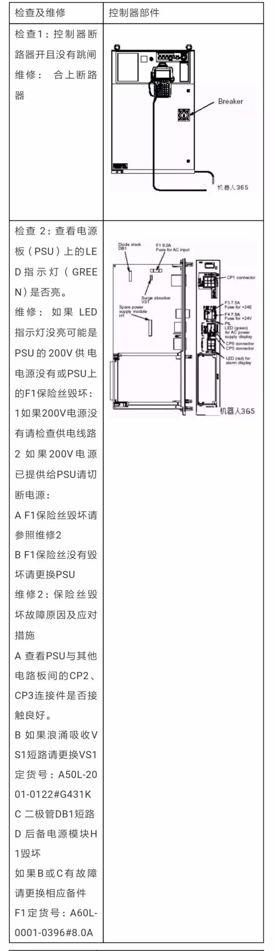
1. Unable to Power On
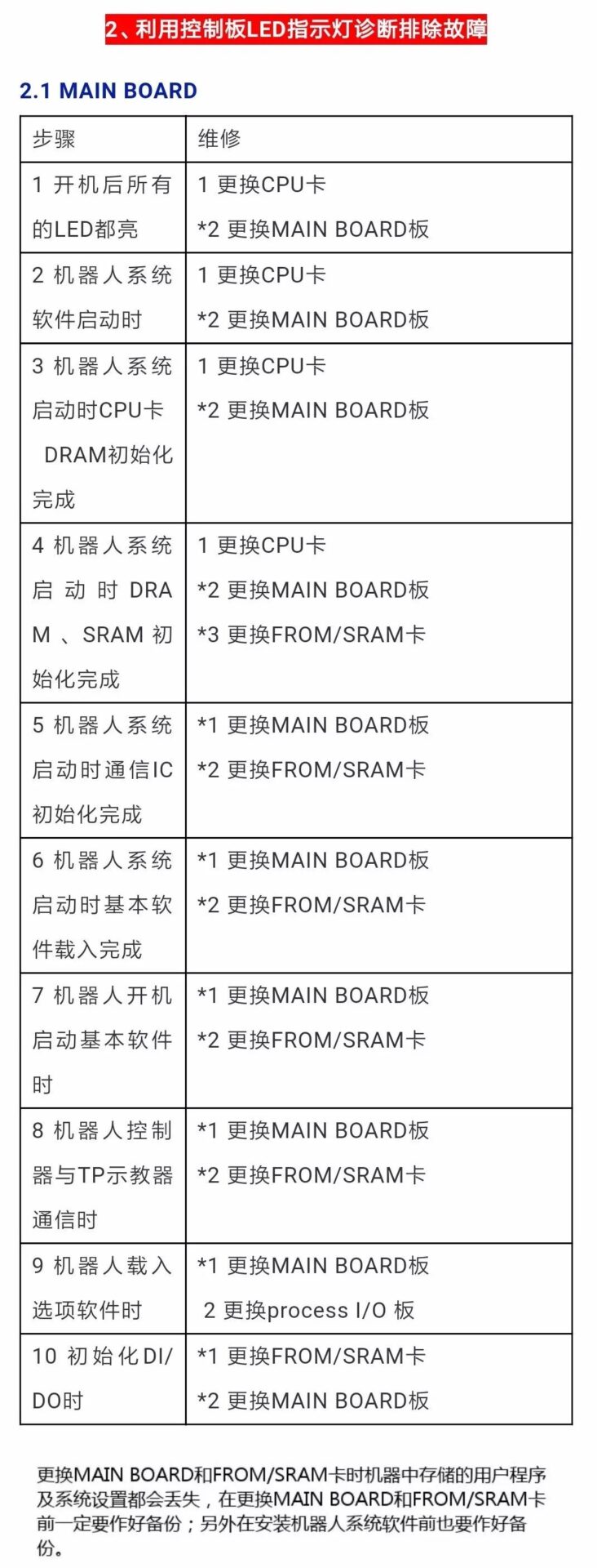
When replacing the MAIN BOARD and FROM/SRAM card, the user program and system settings stored in the machine will be lost. Make sure to back up before replacing the MAIN BOARD and FROM/SRAM card; also, back up before installing the robot system software.
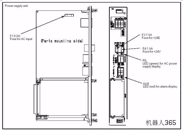
2.2 PSU LED Indicators
|
Fault Description and Response Measures |
|
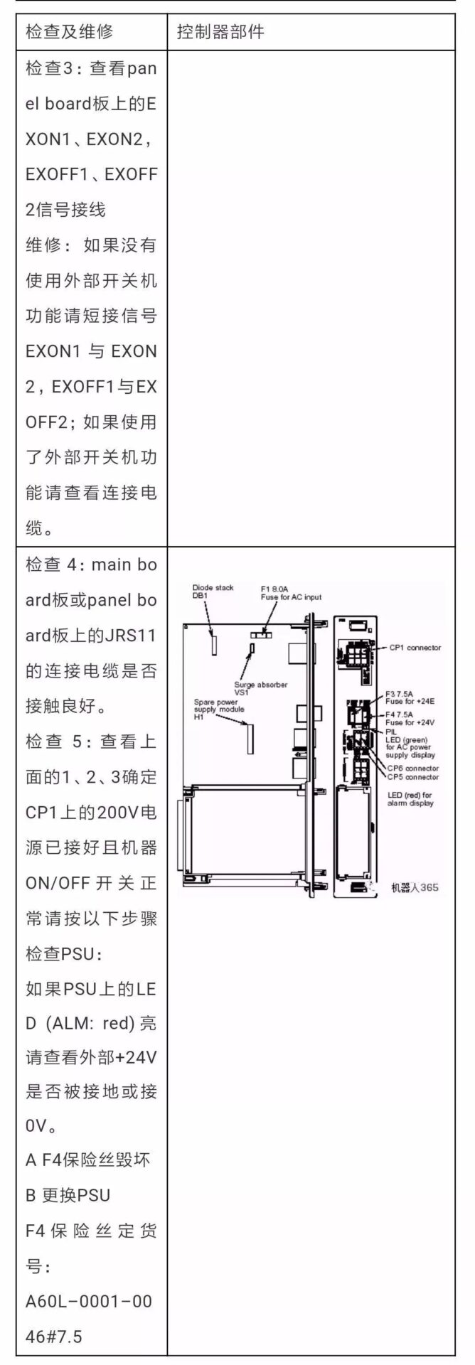
Fault: ALM LED (red) lights up, PSU alarm Measure 1: Check the F4 (+24V) fuse on the PSU, replace if damaged Measure 2: Check the +5V, +15V, +24V voltages on the PSU and related cables and devices, replace if damaged Measure 3: Replace the PSU |
|
Fault: PIL LED (Green) does not light up, 200V power supply of PSU is missing Measure 1: Check the F1 fuse on the PSU, replace if damaged Measure 2: Replace the PSU |
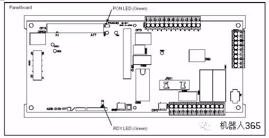
2.3 PANEL BOARD LED Indicators
|
LED |
Fault and Response Measures |
|
RDY |
Fault: This LED (GREEN) does not light up, indicating a communication interruption between the PANEL BOARD and MAIN BOARD Measure 1: Check the communication cable between the MAIN BOARD and PANEL BOARD, replace if damaged Measure 2: Replace the MAIN BOARD Measure 3: Replace the PANEL BOARD |
|
PON |
Fault: This LED does not light up, indicating failure to convert +24V voltage to +5V voltage on the PANEL BOARD Measure 1: Check the CRM63 connector, +24V input power supply Measure 2: Replace the PANEL BOARD |
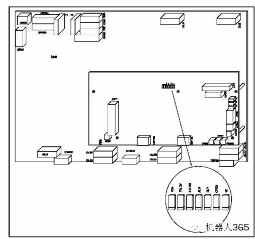
2.4 PROCESS I/O LED Indicators
|
LED |
Fault and Response Measures |
|
Process I/O CA/CB/DA |
Fault: Communication error between MAIN BOARD and PROCESS I/O board Measure 1: Replace the I/O board Measure 2: Replace the MAIN BOARD Measure 3: Replace the I/O communication cable |
|
Process I/O CA/CB/DA |
Fault: I/O board fuse is damaged Measure 1: Replace the fuse Measure 2: Check peripheral cables Measure 3: Replace the I/O board |
2.5 Servo Amplifier LED Indicators
|
LED |
Color |
Description |
|
P5V |
Green |
On: Servo amplifier +5V power supply is normal Off: 1; Check robot RP1 connection cable 2; Replace the servo amplifier |
|
P3.3V |
Green |
On: Servo amplifier +3.3V power supply is normal Off: Replace the servo amplifier |
|
SVEMG |
Red |
On: Robot has an emergency stop signal input (replace if there is no emergency stop signal input) Off: Robot is normal (replace servo amplifier if there is an emergency stop signal) |
|
ALM |
Red |
On: Servo amplifier fault alarm |
|
RDY |
Green |
On: Servo amplifier ready to drive the motor Off: If the motor can operate, replace the servo amplifier |
|
OPEN |
Green |
On: Communication between servo amplifier and MAIN BOARD is normal Off: 1; Check communication cable connection between servo amplifier and MAIN BOARD 2; Replace the servo control card 3; Replace the servo amplifier |
|
WD |
Red |
On: 1; Replace the servo amplifier 2; Replace the servo control card 3; Replace the CPU card 4; Replace the MAIN BOARD |
|
D7 |
Red |
On: 1; Check internal cables of the controller 2; Replace the emergency stop board 3; Replace the servo amplifier |


400-6767-076

Mr. Zhang: 138-1827-1188
Ms. Hu: 137-6473-3309