Click the blue "Arm Selection" in the upper left corner and choose "Set as Star"1 Overview
This article introduces memory translation in Armv8-A, which is key to memory management. It explains how virtual addresses are converted to physical addresses, the format of translation tables, and how software manages Translation Lookaside Buffers (TLB).
This is useful for anyone developing low-level code (such as boot code or drivers). It is particularly relevant for anyone writing code to set up or manage a Memory Management Unit (MMU).
2 What is memory management?
Memory management describes how access to system memory is controlled. Each time an operating system or application accesses memory, hardware performs memory management. Memory management is a way to dynamically allocate memory regions to applications.
2.1. Why is memory management needed?
Application processors are designed to run rich operating systems like Linux and support virtual memory systems. Software executing on the processor can only see virtual addresses, which the processor converts to physical addresses. These physical addresses are presented to the memory system and point to actual physical locations in memory.
3 Virtual and physical addresses
The benefit of using virtual addresses is that it allows management software, such as the operating system (OS), to control the view of memory presented to software. The operating system can control which memory is visible, the virtual addresses visible for that memory, and what accesses are allowed to that memory. This allows the operating system to sandbox applications (hiding the resources of one application from another) and provides an abstraction of the underlying hardware.
One advantage of using virtual addresses is that the operating system can present multiple fragmented physical memory regions as a single, contiguous virtual address space to applications.
Virtual addresses are also beneficial for software developers, who do not need to know the exact memory addresses of the system when writing applications. With virtual addresses, software developers do not need to worry about physical memory. The application knows that address translation is done jointly by the operating system and hardware.
In fact, each application can use its own set of virtual addresses that map to different locations in the physical system. When the operating system switches between different applications, it remaps. This means that the virtual addresses of the current application will map to the correct physical locations in memory.
Virtual addresses are mapped to physical addresses. The mapping between virtual and physical addresses is stored in translation tables (sometimes referred to as page tables), as shown in the figure below: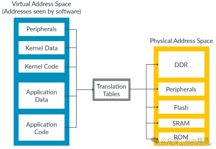 Translation tables are managed in memory by software, typically the operating system or hypervisor. The translation tables are not static and can be updated as software demands change. This changes the mapping between virtual and physical addresses.
4 The Memory Management Unit (MMU)
The Memory Management Unit (MMU) performs address translation. The MMU contains the following:
-
The table walk unit: It reads page tables from memory and completes address translation.
-
Translation Lookaside Buffers (TLBs): Caches, equivalent to cache.
All memory addresses seen by software are virtual. These memory addresses are passed to the MMU, which checks the recently used cached translations in the TLB. If the MMU does not find the recently cached translation, the table walk unit reads the appropriate one or more table entries from memory, as shown below: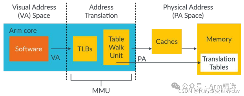 Before performing memory access, the virtual address must be converted to a physical address (because we must know which physical memory location we are accessing). This conversion must also apply to cached data, as data caches on Armv6 and later processors use physical addresses (physical-tagged addresses) to store data. Therefore, the address must be converted first before completing the cache lookup.
Note: The architecture is a behavioral specification. The cache must behave as if it were physically tagged. An implementation may do some different things as long as it is not visible to software.
4.1. Table entry
The translation tables work by dividing the virtual address space into equally sized blocks and providing an entry for each block in the table.
Entry 0 in the translation tables provides the mapping for block 0, entry 1 provides the mapping for block 1, and so on. Each entry contains the address of the corresponding physical memory block and the attributes to be used when accessing the physical address.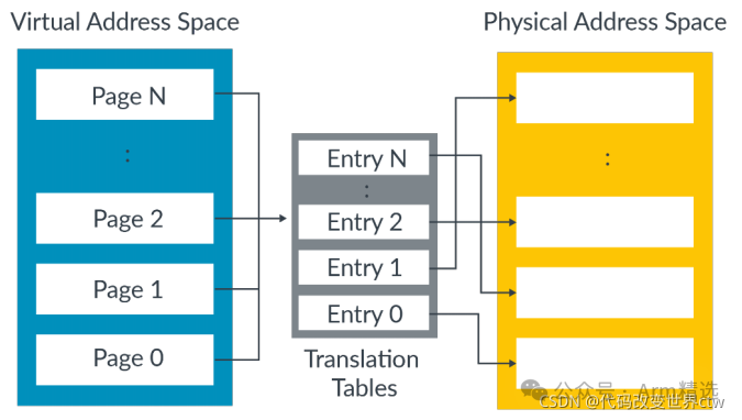
4.2. Multilevel translation
In a single-level lookup, the virtual address space is divided into equally sized blocks. In practice, a hierarchy of tables is used.
The first table (Level 1 table) divides the virtual address space into large chunks. Each entry in this table can point to a physical memory block of equal size or another table that subdivides that block into smaller blocks. We call this type of table a “multilevel table.” Here we can see an example of a multilevel table with three levels: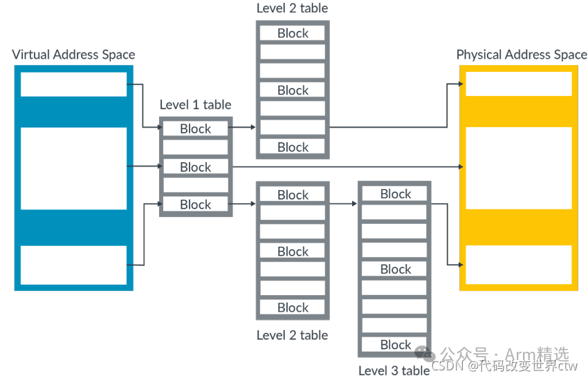 In Armv8-A, the maximum number of levels is 4 (nonsense!! This is incorrect, just take a look), with level numbering from 0 to 3. This multilevel approach allows for the description of larger and smaller blocks. The characteristics of large and small blocks are as follows:
-
Large blocks require fewer read levels to translate than small blocks. Additionally, caching large blocks in the TLB is more efficient. —This feature is well understood, which is great
-
Small blocks provide software with fine-grained control over memory allocation. However, caching small blocks in the TLB is less efficient. Caching efficiency is lower because small blocks require multiple reads through levels to be translated.
To manage this trade-off, the operating system must balance the efficiency of using large mappings against the flexibility of using smaller mappings for optimal performance.
Note: The processor does not know the size of the translation when it starts looking up the table. The processor calculates the size of the block being translated by performing a table walk.
5 Address spaces in Armv8-A
There are several independent virtual address spaces in Armv8-A. This diagram shows these virtual address spaces: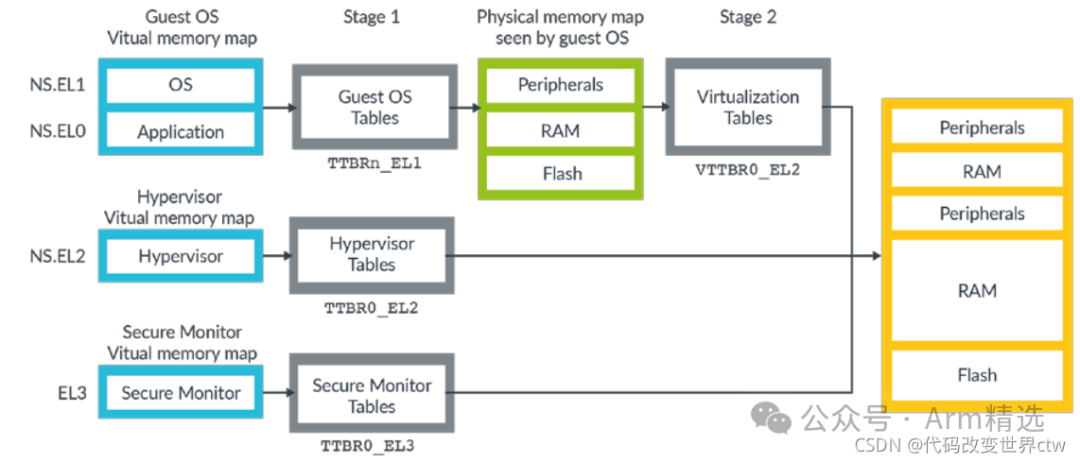 The diagram shows three virtual address spaces:
-
NS.EL0 and NS.EL1 (Non-secure EL0/EL1).
-
NS.EL2 (Non-secure EL2).
-
EL3.
Each of these virtual address spaces is independent and has its own settings and tables. These settings and tables are often referred to as “translation regimes.” Secure EL0, Secure EL1, and Secure EL2 also have virtual address spaces, but they are not shown in the diagram. (Note: Support for Secure EL2 was added in Armv8.4-A)
Because there are multiple virtual address spaces, it is important to specify which address space an address belongs to. For example, NS.EL2:0x8000 refers to address 0x8000 in the Non-secure EL2 virtual address space.
The diagram also shows that virtual addresses from Non-secure EL0 and Non-secure EL1 go through two sets of tables. These tables support virtualization and allow the hypervisor to virtualize the view of physical memory seen by virtual machines (VMs).
In virtualization, we refer to a set of translations controlled by the operating system as stage 1. The stage 1 table translates virtual addresses to Intermediate Physical Addresses (IPA). In stage 1, the operating system treats the IPA as the physical address space. However, the hypervisor controls the stage 2 translations. The stage 2 translation converts the IPA to a physical address. This diagram shows how the two sets of translations work: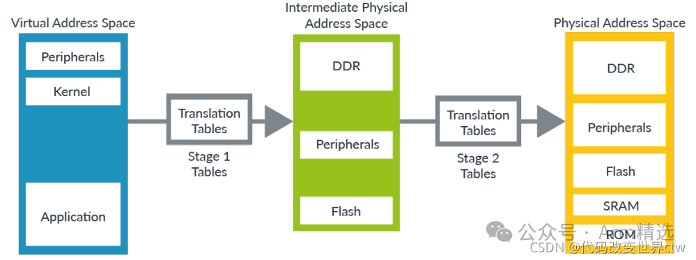 While there are some subtle differences in table format, the processes for Stage 1 and Stage 2 translations are generally the same.
Note: In Arm, we often use the address 0x8000 in many examples. 0x8000 is also the default address linked with the Arm linker armlink. This address comes from the early microcomputer BBC Micro Model B, which had ROM (and lateral RAM) at address 0x8000. The BBC Micro Model B was made by a company called Acorn, which developed the Acorn RISC Machine (ARM), later renamed Arm.
5.1. Address sizes
Armv8-A is a 64-bit architecture, but this does not mean that all addresses are 64 bits.
5.1.1 Size of virtual addresses
Virtual addresses are stored in 64-bit format. Therefore, addresses in load instructions (LDR) and store instructions (STR) are always specified in the X registers. However, not all addresses in the X registers are valid. The following diagram illustrates the layout of the virtual address space in AArch64: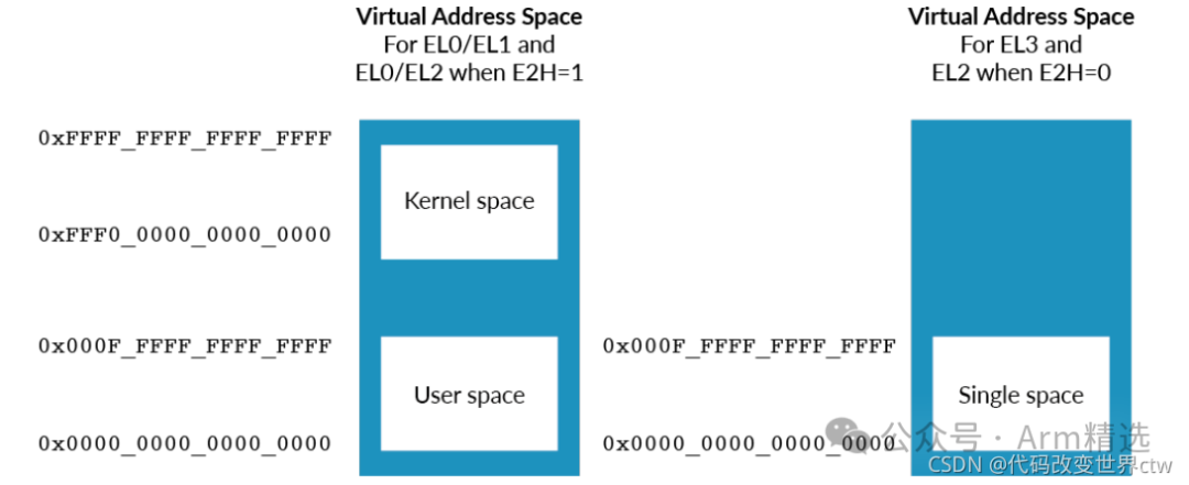 The EL0/EL1 virtual address space has two regions: kernel space and application space. These two regions are shown on the left side of the diagram, with the kernel space at the top and the application space (marked as “user space”) at the bottom. The kernel space and user space have separate translation tables, meaning their mappings can be separated.
Note: If you set HCR_EL2.E2H to 1, the configuration will enable the host operating system to run in EL2, while the applications of the host operating system run in EL0. In this case, EL2 also has upper and lower regions.
The size of each region is determined by the effective bits of the virtual address, which is configured by TCGEL1.TxSZ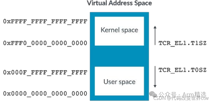 Note: All Armv8-A implementations support 48-bit virtual addresses. Support for 52-bit virtual addresses is optional and can be obtained from IDAA64MMFR2_EL1.
5.1.2 Size of physical addresses
The size of physical addresses is implementation-defined, up to 52 bits. The IDAA64MMFR0EL1 register reports the size of the processor implementation. For Arm Cortex-A processors, this is typically 40 bits or 44 bits.
Note: In Armv8.0-A, the maximum size of physical addresses is 48 bits. This was extended to 52 bits in Armv8.2-A.
5.1.3 Size of intermediate physical addresses
If the output address specified in the translation table entry exceeds the maximum defined by the implementation, the Memory Management Unit (MMU) will generate an exception as an address size error.
The size of the IPA space can be configured in the same way as the virtual address space.<span><span>VTCR_EL2</span></span><span><span>.</span></span><span><span>T0SZ</span></span> controls the size. The maximum configurable size is the same as the physical address size supported by the processor. This means you cannot configure an IPA space larger than the supported physical address space.
5.2. Address Space Identifiers – Tagging translations with the owning process
Many modern operating systems seem to run all applications from the same address region, which we describe as user space. In reality, different applications need different mappings. For example, this means that the translation of VA 0x8000 depends on which application is currently running.
Ideally, we want the translations of different applications to coexist in the Translation Lookaside Buffer (TLB) to avoid needing to invalidate the TLB during context switches. But how does the processor know which version of the VA 0x8000 translation to use? In Armv8-A, the answer is the Address Space Identifier (ASID).
For the EL0/EL1 virtual address space, translations can be tagged as global (G) or non-global (nG) using the nG bit in the attribute field of the translation table entry. For example, kernel mappings are global translations, while application mappings are non-global translations. Global translations apply to any application currently running. Non-global translations apply only to specific applications.
Non-global mappings use ASID for tagging in the TLB. During a TLB lookup, the ASID in the TLB entry is compared with the currently selected ASID. If they do not match, the TLB entry is not used. The diagram shows global mappings in the kernel space without ASID tags and non-global mappings in the user space with ASID tags: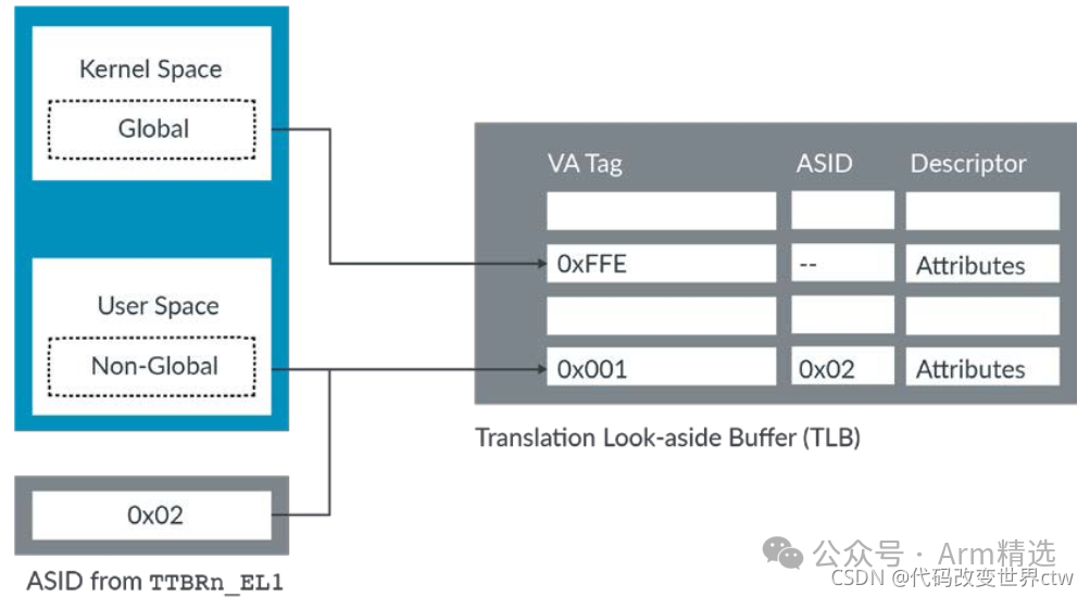 This diagram shows how TLB entries allow multiple applications to coexist in the cache, with ASID determining which entry to use. The ASID is stored in one of the two TTBRnEL1 registers. Typically, TTBR0EL1 is used for user space. Therefore, a single register update can change the ASID and the translation table it points to.
Note: ASID tagging is also available in EL2 when HCR_EL2.E2H==1.
5.3. Virtual Machine Identifiers – Tagging translations with the owning VM
EL0/EL1 translations can also be tagged with Virtual Machine Identifiers (VMID). VMID allows translations from different VMs to coexist in the cache. This is similar to how ASID works for translations from different applications. In fact, this means that some translations will be tagged with both VMID and ASID, and both must match for the TLB entry to be used.
Note: When secure state supports virtualization, EL0/EL1 translations are always tagged with VMID—even if Stage 2 translations are not enabled. This means that if you are writing initialization code and not using a hypervisor, it is important to set a known VMID value before setting up the Stage 1 MMU.
5.4. Common not Private
If a system contains multiple processors, do ASID and VMID used on one processor have the same meaning on other processors?
For Armv8.0-A, the answer is that they do not necessarily mean the same thing. Software is not required to use a given ASID in the same way across multiple processors. For example, ASID 5 might be used by a calculator on one processor and a web browser on another processor. This means that TLB entries created by one processor cannot be used by another processor.
In practice, it is unlikely that software will use different ASIDs across processors. It is more common for software to use ASID and VMID in the same way across all processors in a given system. Therefore, Armv8.2-A introduced the Common not Private (CnP) bit in the translation table base registers (TTBR). When the CnP bit is set, software commits to using ASID and VMID in the same way across all processors, allowing another processor to use TLB entries created by one processor.
Note: We have been talking about processors, but technically we should use the term processing element (PE). PE is a generic term for any machine implementing the Arm architecture. This is important because sharing TLBs across processors can be difficult due to microarchitectural reasons. However, in multithreaded processors, each hardware thread is a PE, making it more desirable to share TLB entries.
6 Controlling address translation
6.1. Translation table format
Here we can see that translation table entries have four different formats (nonsense!! Actually, there are 3 types; block descriptor and page descriptor are actually one type):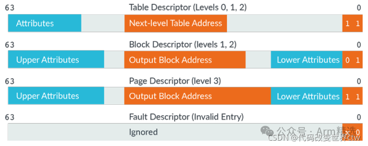 Note: For clarity, this diagram does not specify the width of the field bits. You can find this information in the Arm architecture reference manual Armv8, applicable to the Armv8-A architecture profile: VMSAv8-64 translation table format descriptors.
Each entry is 64 bits, and the bottom two bits determine the type of entry.
Note that some table entries are only valid at specific levels. The maximum number of levels for the table is four, which is why Level 3 (or the fourth level) table does not have table descriptors. Similarly, Level 0 does not have block descriptors or page descriptors. Because Level 0 entries cover a large area of the virtual address space, allowing blocks is meaningless.
Note: The encoding of Level 0-2 table descriptors is the same as that of Level 3 page descriptors. This encoding allows for “recursive tables” that point to themselves. This is useful as it easily calculates the virtual address of a specific page table entry so that it can be updated.
7 Translation granule
A translation granule is the smallest memory block that can be described. Smaller things cannot be described; only larger blocks, which are multiples of the granules, can be described.
Armv8-A supports three different granularities: 4KB, 16KB, and 64KB.
The granularity supported by the processor is implementation-defined and reported by IDAA64MMFR0EL1. All Arm Cortex-A processors support 4KB and 64KB. The selected granularity is the smallest block that can be described in the latest level table. Larger blocks can also be described. The following table shows the different block sizes of each level table based on the selected granularity: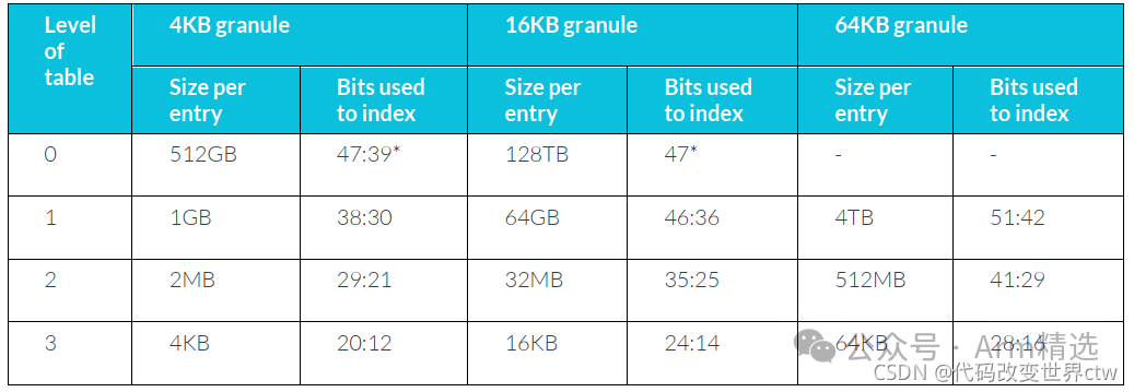 (Asterisk*) Using a 52-bit address has restrictions. When the selected granule is 4KB or 16KB, the maximum virtual address area size is 48 bits. Similarly, the output physical address limit is 48 bits. Only when using a 64KB granule can the full 52 bits be used.
Note: TCR_EL1 has two separate fields to control the granule size of the virtual address ranges for kernel space and user space. These fields are referred to as TG1 for kernel space and TG0 for user space. A potential issue for programmers is that these two fields have different encodings.
7.1. The starting level of address translation
The granularity and size of the virtual address space together control the starting level of address translation.
The table above summarizes the block sizes for each level of the table at each granularity (the size of the virtual address range covered by a single entry). From the block size, you can calculate which bits of the virtual address are used to index each level of the table.
We take 4KB granules as an example. This diagram shows the bits used to index different level tables for 4KB granules: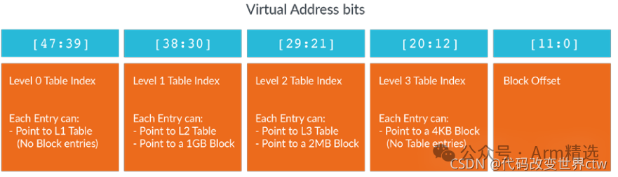
7.2. Registers that control address translation
Address translation is controlled by a combination of system registers: (1) SCTLR_ELx
-
M – Enable Memory Management Unit (MMU).
-
C – Enable for data and unified caches.
-
EE – Endianness of translation table walks.
(2) TTBR0ELx and TTBR1ELx
-
BADDR – Physical address (PA) (or intermediate physical address, IPA, for EL0/EL1) of the start of the translation table.
-
ASID – The Address Space Identifier for Non-Global translations.
(3) TCR_ELx
-
PS/IPS – Size of PA or IPA space, the maximum output address size.
-
TnSZ – Size of address space covered by the table.
-
TGn – Granule size.
-
SH/IRGN/ORGN – Cacheability and shareability to be used by MMU table walks.
-
TBIn – Disabling of table walks to a specific table.
(4) MAIR_ELx
-
Attr – Controls the Type and cacheability in Stage 1 tables.
7.3. MMU disabled
When the MMU is disabled in a translation stage, all addresses are one-to-one mapped. Flat mapping means that the input and output addresses are the same.
8 Translation Lookaside Buffer maintenance
The Translation Lookaside Buffers (TLBs) cache recently used translations. This caching allows subsequent lookups to reuse translations without re-reading the tables.
Note: TLB is a translation cache, not a translation table cache. The distinction is subtle. Several register fields control how translation table entries are interpreted. The contents of a TLB entry are the interpretation of the translation table entry given the configuration during table traversal. Such register fields are described in the Arm architecture reference manual (Arm ARM) as “allowing caching in the TLB.”
If translation table entries or controls that affect the way entries are interpreted are changed, the affected entries in the TLB need to be invalidated. If you do not invalidate these entries, the processor may continue to use the old translations.
The processor does not allow caching to the TLB that causes any of the following errors:
-
A translation fault (unmapped address).
-
An address size fault (address outside of range).
-
An access flag fault
Therefore, it is not necessary to issue a TLB invalidate when first mapping an address. However, if you want to perform any of the following actions, you do need to issue a TLB invalidate:
-
Unmap an address Take an address that was previously valid or mapped and mark it as faulting.
-
Change the mapping of an address Change the output address or any of the attributes. For example, change an address from read-only to read-write permissions.
-
Change the way the tables are interpreted This is less common. But, for example, if the granule size was changed, then the interpretation of the tables also changes. Therefore, a TLB invalidate would be necessary.
8.1. Format of a TLB operation
TLBI instructions are used to invalidate entries in the TLB. The syntax of this instruction is:<span><span>TLBI</span></span><span><span><type><level></span></span><span><span>{</span></span><span><span>IS</span></span><span><span>|</span></span><span><span>OS</span></span><span><span>}</span></span><span><span>{,</span></span><span><span><xt></span></span><span><span>}</span></span>
9 Address translation instructions
Address translation (AT) instructions allow software to query the translation for a specific address. The resulting translation (including attributes) is written to the physical address register PAR_EL1.
The syntax of AT instructions allows you to specify which translation mechanism to use. For example, EL2 can query the EL0/EL1 translation mechanism. However, EL1 cannot use AT instructions to query the EL2 translation mechanism, as this would violate privilege.
If the requested translation causes an error, no exception is generated. Instead, the type of fault generated is recorded in PAR_EL1.
💋💋💋 Related course introduction: Mastering ARM to Impress Your Leaders: “From Beginner to Mastering Armv8/Armv9 Architecture (Phase III)”💋💋💋🌍 Consult vx: sami01_2023