Click the card below to follow Arm Technology Academy
This article is organized by the WeChat public account Arm Selected, and mainly shares the related content of Armv8 Cache Coherency Solution: MOESI protocol.
1. MOESI State Definitions
The Armv8 architecture uses the MOESI protocol to maintain data consistency between multiple cores. The MOESI protocol describes the state of a shared cache line in the L1 Data Cache as:
●M, Modified, Unique Dirty, exists only in the current cache (unique), and the data in this cache line is different from the data in the next level storage (dirty). In other words, the latest data in the cache line is located in the current cache, and there are no backups in other caches, making the content of the cache line inconsistent with the main memory.
●O, Owned, Shared Dirty, describes a cache line as dirty and may exist in multiple caches (more than one). An Owned state cache line holds the latest and correct data. Only one core’s cache can keep the data in the Owned state, while other cores are in the shared state.
●E, Exclusive, Unique Clean, the data exists only in the current cache line and is clean. The data in the cache line is consistent with the main memory, and there are no backups of this address in other cores’ caches, existing in only one cache.
●S, Shared, Shared, the data in the cache line may not be consistent with the main memory, corresponding to the Owned state cache line, copying the data from the Owned cache line to the shared cache line, so the data in the shared cache line is also the latest.
●I, Invalid, invalid data.
The Data Cache Unit (DCU) will store the MOESI state information of the cache line in tag RAM and dirty RAM.
2. MOESI State Transitions
The following diagram shows the state transition diagram of the MOESI protocol.
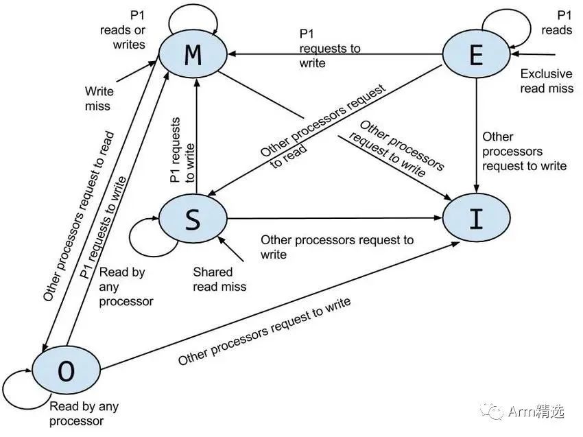
Figure 1
Next, this article will explain the specific MOESI state transitions combined with a state transition use case.
2.1 Invalid after Reset
Assuming the current system has four cores, each core has its own independent data cache. After the system powers on, all cores’ cache lines are in the invalid state:
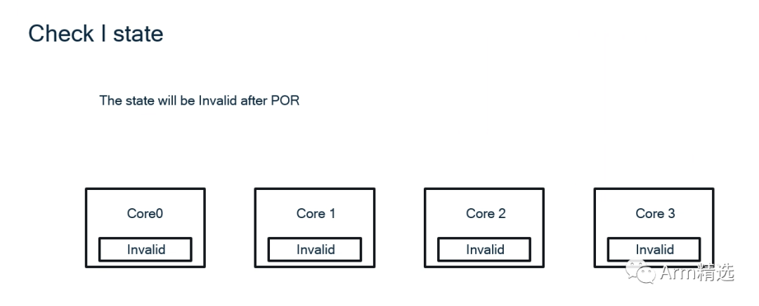
Figure 2
2.2 Invalid=>Exclusive
Then core0 attempts to read data at the memory address 0x44013F00. The state of the cache line related to this address in core0’s cache will change from Invalid to VE, where V stands for Valid, indicating that the data in this cache line is valid. E stands for Exclusive, indicating that the data is only in core0.
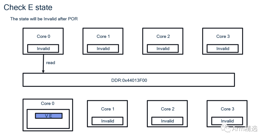
Figure 3
2.3 Exclusive=>Modified
Afterwards, core0 attempts to write a new value to this address, causing the cache line’s state to change from VE to VDM, where V stands for valid, D stands for Dirty, indicating that the data is dirty and the data in the current cache line is inconsistent with the main memory. M stands for Modified, indicating that the data in the cache line is Unique and Dirty.
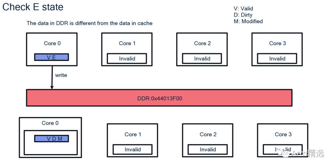
Figure 4
2.4.1 Modified=>Owned, Invalid=>Shared
Next, when core1, core2, and core3 read from this address, core0’s state will change from VDM to VDO, and the cache lines of the other three cores will change from Invalid to VS, where O stands for Owned and S stands for Shared. The O state and S state are corresponding. Moreover, from the following diagram, it can be seen that the data read by core1, core2, and core3 is a backup from core0’s cache, not the actual value in the memory.
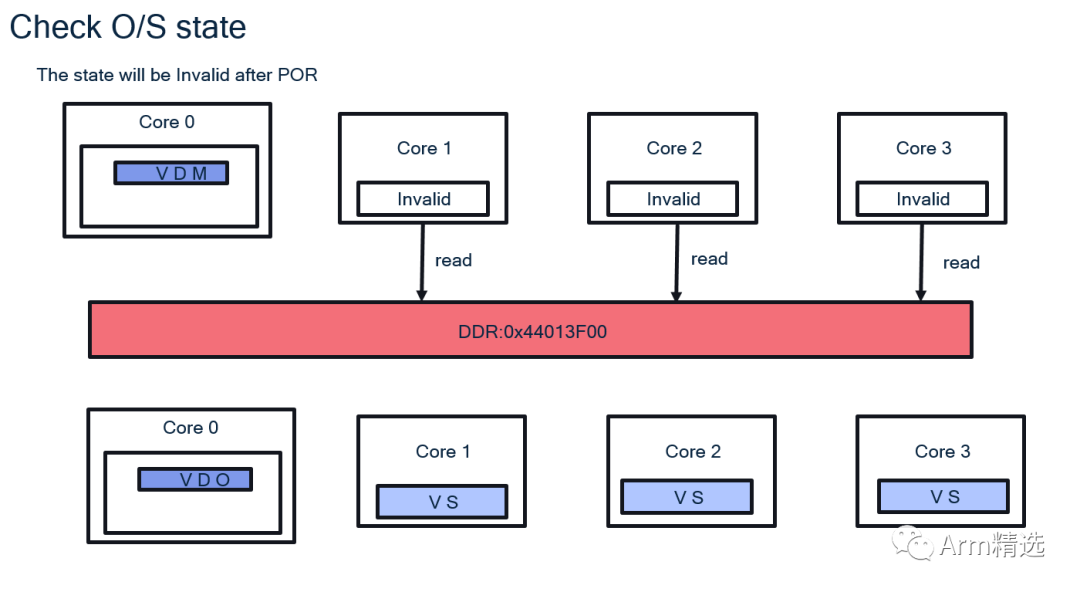
Figure 5
2.4.2 Modified=>Invalid, Invalid=>Modified
If core1 writes a new piece of data, the data in core0 will not be written back to DDR, causing data corruption, and the previously stored data in core0 disappears, changing the cache line’s state to invalid. Meanwhile, core1’s state will change from Invalid to Modified, which is also dirty.
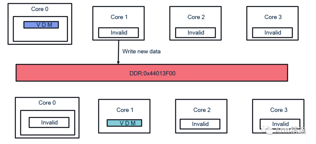
Figure 6
2.5 Owned=>Invalid, Shared=>Invalid, Shared=> Modified
Following the steps of 4.1, if core1 attempts to write a new value to this address, core0’s state will change from Owned to Invalid, the cache line states in core2 and core3 will change from Shared to Invalid, while core1’s state will change from Shared to Modified (VDM). Moreover, since a write-back strategy is used, the current write operation only writes to the cache, and the content in the main memory remains unchanged.
In this example, two cores perform read and write operations on the same memory address sequentially. The value written by core0 (in blue) is not written back to the main memory, and then core1 writes a new value (in green) to that address, overwriting the value written by core0.
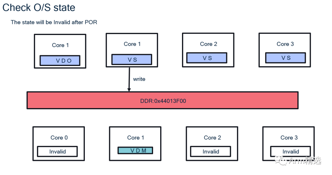
Figure 7
2.6 Clean and Invalidate Operations Impact on MOESI State
2.6.1 Clean & Invalidate on Owned State
As shown in the figure below, core0’s related cache line was previously in the VDO state. After performing clean & invalidate operations, core0’s state changes to Invalid, while the other three cores remain in the VS state, and the data in core0’s cache has been written back to the main memory.
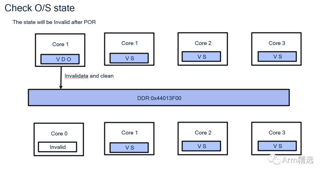
Figure 8
2.6.2 Clean & Invalidate on Shared State
As shown in the figure below, core1’s related cache line was previously in the VS state. After performing clean & invalidate operations, core1’s state changes to Invalid, while the other two cores remain in the VS state, and the data in core1’s cache has been written back to the main memory. However, core0’s related cache line remains in the VDO state. At this point, the data in the main memory and the data in the cache have been synchronized, but core0’s cache line remains in the dirty state. This is because the Clean & Invalidate operation is actively performed by software, interfering with the normal data synchronization process at the hardware level.
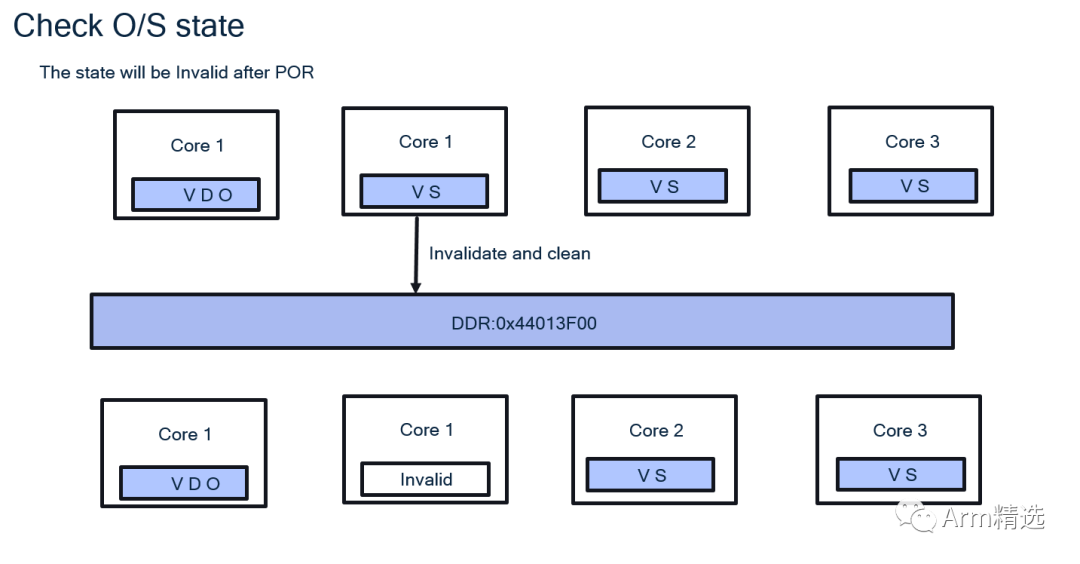
Figure 9
3. Notes
Maintaining data consistency at the hardware level requires enabling the CPU Extended Control Register’s SMPEN bit, which provides additional processor configuration and control options. Among them, the SMPEN bit:
CPUECTLR[6]: SMPEN, enables hardware management of data consistency across multiple cores in the current cluster. When set to 0, it disables the data consistency maintenance function across multiple cores, which is also the reset value. When set to 1, it enables data consistency functionality. Therefore, even in a system with only one core, it is recommended to set SMPEN to 1 before enabling the cache; otherwise, the data in the cache will not synchronize with other cores, which may lead to data corruption.
Reference article: DDI0500J_cortex_a53_trm.pdf Recommended Reading
-
A paper explaining Cache Optimization
-
A brief overview of the basic concepts and use cases of cache
-
Analysis of the architecture of Arm Cortex-A53 cache



Long press to identify the QR code to add Miss Ji’s WeChat (aijishu20) and join the Arm Technology Academy reader group.
Follow Arm Technology Academy