
With the background of technological advancements in electrification, intelligence, and connectivity, the electronic and electrical architectures across various industries are undergoing profound transformations. New architectures are gradually replacing traditional ones in fields such as automotive, engineering machinery, energy storage, and shipping, transitioning from traditional distributed architectures to domain-centric and even central-centric models, with controller functions becoming more centralized and complex. To enhance development efficiency, improve software stability, and facilitate platform portability, developing complex software based on the AutoSar architecture has become an industry consensus.
Moreover, competition within the industry is becoming increasingly fierce, with significantly compressed development cycles. Coupled with the rising complexity of software, ensuring software quality during rapid iterations has become a critical issue. Additionally, with the requirements of process frameworks and regulatory standards such as ASPICE and ISO26262, how to develop application software that complies with the AutoSar architecture, assess software quality and performance, optimize software structure, and verify ECU stability under pressure scenarios has become a new challenge faced by manufacturers.
This article focuses on the development of application software compliant with the AutoSar architecture, software quality assessment and optimization solutions under the Model-Based Design (MBD) development model, and ECU performance stress testing solutions in complex scenarios.
Introduction to Application Software Development Compliant with AutoSar Architecture
For the AutoSar software architecture, it is divided into the classic platform AutoSar CP and the adaptive platform AutoSar AP, which have different application scenarios: AutoSar CP is characterized by high safety and real-time performance, typically deployed on microcontroller (MCU) type chips or multi-core heterogeneous chips; AutoSar AP features dynamism and scalability, suitable for applications involving large data parallel processing and high-performance computing, usually deployed on MPU or multi-core heterogeneous chips. Currently, in the industry, whether for domain controllers or central + regional controllers, they are typically multi-core, and even multi-core heterogeneous, with different cores deploying AutoSar CP or AP based on actual usage needs, while the basic software usually adopts standard BSW protocol stacks. The following diagram illustrates an example of the AutoSar software architecture:
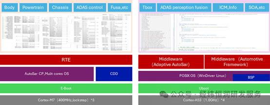
AutoSar Software Architecture
For application layer software, if one wants to develop software compliant with the AutoSar architecture, two important questions need to be considered:
-
What development toolchain to use
-
What development model to adopt
For the application software development toolchain, it typically involves SWC software architecture design tools and software programming implementation tools. SWC software architecture design tools mainly implement the application layer software architecture, define SWC, configure SWC interaction interfaces, configure Runnables, export ARXML files, etc. Generally, different brands of protocol stacks have corresponding SWC software architecture design tools, and the self-developed AutoSar protocol stack by Hirain provides a toolchain solution called EAS-SWCDesigner.
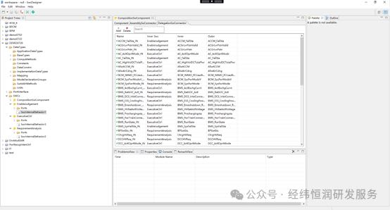
EAS-SWCDesigner Interface
Software programming implementation can be based on graphical programming for automatic code generation or handwritten code. The implementation methods for application layer software development under AutoSar CP and AP architectures differ slightly; CP architecture application layers more often adopt model-based design methods, with toolchains typically using Matlab/Simulink, which provides comprehensive and mature support for CP architecture application layer development. However, due to its incomplete support for AP architecture application software development, AP architecture application layer software development currently still relies more on handwritten C++ code, with toolchains based on various code editing tools like Vscode.
Regarding the application software development model, it can be divided into top-down development, bottom-up development, and bidirectional development models. Top-down development is more suitable for forward development processes, adopting this model when there is input from the EE architecture. The advantage of this model is that it can inherit the work products of the EE architecture, but the downside is that the work chain can be relatively long, requiring both application layer and lower layer software development to rely on the ARXML files exported from the SWC architecture design, which affects development iteration efficiency. Bottom-up development directly implements software in the programming tools, then configures the AutoSar interfaces, exports ARXML, and merges the ARXML files. This method is more suitable for situations without EE architecture input, allowing application software development engineers to independently configure AutoSar interfaces. The advantage of this model is that it does not rely on the AutoSar toolchain, making it more flexible, but the downside is that it requires a higher level of AutoSar knowledge from each application software developer. The bidirectional development model combines the advantages of both top-down and bottom-up development models, using the top-down development model for the first version of the software and adopting the bottom-up development model for subsequent software updates and iterations.
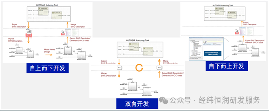
Application Software Development Model
Software Quality Assessment and Optimization Solutions under MBD Development Model
MBD stands for Model-Based Design, which is a development approach primarily based on visual model development, contrasting with traditional code development mediated by text coding. Using a model-based approach to describe control algorithm design has made significant progress in terms of readability, maintainability, portability, and ease of testing and verification compared to previous manual C code. Given these characteristics of model-based development, the model-based + automatic code generation approach based on Simulink is gradually evolving into a standard configuration in the automotive electronics industry. Consequently, how to ensure software quality under the MBD development approach has become a hot topic of discussion.
A direct and effective means to ensure software quality is to conduct comprehensive testing or optimize the software structure during the software development process to reduce the introduction of issues.
How to Conduct Comprehensive Model Testing?
Model verification methods can be divided into static verification and dynamic verification. Static verification of models is a testing method that verifies whether the model design complies with rules through modeling rule guidelines provided by companies like MAAB and dSPACE. Additionally, there is a model metric check method that can analyze the complexity of the model to assess its quality characteristics in terms of maintainability, portability, and reusability. In summary, there are two methods for model static verification: modeling specification rule checks and model metric checks. Unlike model static verification, model dynamic verification can be conducted by comparing the output values during the execution of the actual model. Dynamic verification of the model is performed by comparing the actual model results with the expected results based on user inputs. By checking the model’s coverage, the coverage of test cases against requirements and the sufficiency of test cases can be improved. Furthermore, by incorporating process management thinking from ASPICE throughout the testing process, the reliability of the testing process, testing environment, testing strategy, and the sufficiency, consistency, and traceability of test cases can be ensured, thereby ensuring model quality.
How to Optimize Software Structure?
Currently, the generated code from our models may have the following issues:
-
A single function in the generated code may exceed tens of thousands of lines
-
Difficulty in understanding the definitions and process transformations of variables in the code generated by Matlab
-
Should modifications be made to the code generated from the model?
Optimizing software requires that static testing has been conducted to optimize the model structure, ensuring the model structure’s compliance. Generating independent functions for each software design unit and corresponding C files for each software component can ensure the clarity of the structure of the model-generated code. Additionally, not modifying the model-generated code is a maintenance principle in the MBD development process.
In summary, let us look forward to Hirain’s solutions for software quality assessment and optimization under the MBD development model.
ECU Performance Stress Testing Solutions in Complex Scenarios
With the surge in the number of controllers and the increasing complexity of module interactions, solely verifying the basic functionality of software has certain limitations. More and more project practices indicate that sporadic software failures need to be supplemented by verification from software performance metrics and stress scenarios to ensure the quality of software products.
Performance testing analyzes the worst-case conditions for ECU control software’s memory (stack, RAM/ROM/FLASH) and CPU load to ensure reasonable resource usage; stress testing constructs scenarios for communication, IO driving, diagnostics, network management, and other modules with abnormal injections, bus faults, high-frequency triggers, etc., to ensure that software functionality does not pose fatal risks under stress scenarios.
Static Performance Analysis Based on AbsInt
◾ Customer Benefits
-
Evaluate resource usage to guide chip selection and engineering optimization
-
Ensure the reasonableness of task and interrupt reserved stack space and allocation cycles
-
Ensure that chip memory usage and CPU load remain within threshold ranges
-
Conduct tests that comply with functional safety and ASPICE process requirements
◾ Testing Content
-
Memory: Automated analysis of worst-case stack usage, RAM/ROM/Flash occupancy rates
-
WCET: Analyze execution time under worst-case conditions, test cycle stability, and task real-time performance
-
Scheduling Simulation: Simulate task scheduling, model and simulate CPU load rates and task proportions
◾ Solution Features
-
Using AbsInt tools for automated analysis of engineering binary executable files without relying on source code
-
Supports stack and time analysis for various architectures such as PPC, V850, Tricore, ARM
-
Analyzes traversed conditions, with results covering all entry points of the program
-
Graphically displays execution paths and usage proportions under worst-case conditions, guiding performance optimization
-
Does not rely on test cases, high execution efficiency, and short project cycles
-
AbsInt tools meet ASIL D level functional safety standards
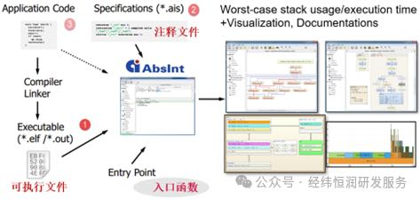
Testing Process Based on AbsInt
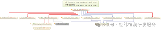
Function Call Relationships and Usage Display
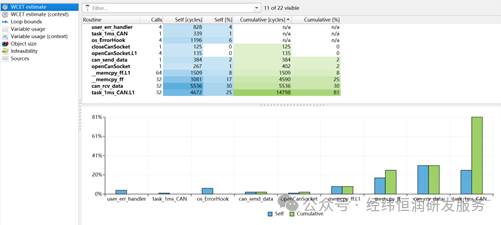
Data Table Usage Display
Dynamic Performance Testing Based on RVS
◾ Customer Benefits
-
Conduct timing analysis in PIL, HIL, and in-vehicle environments to ensure software behavior safety
-
Visual monitoring of task scheduling and CPU load, providing optimization references for system upgrades
-
Ensure the rationality of multi-tasking and multi-core operations, avoiding timing issues such as priority inversion and deadlocks
-
Conduct tests that comply with functional safety and ASPICE process requirements
◾ Testing Content
-
WCET: Analyze the worst-case execution time of tasks/interrupts, test cycle stability, and response real-time performance
-
Task Scheduling: Evaluate WCRT, monitor task timing characteristics, and graphically display multi-core and multi-task scheduling relationships
-
Load Rate: Real-time statistics and analysis of CPU load rates based on actual conditions, assessing CPU load rate occupancy under extreme loads
◾ Solution Features
-
Using the RVS analysis suite for real-time data collection and analysis, restoring execution conditions in actual environments
-
Supports full data collection and long-term monitoring, tracking and locating software-hardware interaction situations
-
Highly customizable, strong project reusability, capable of timing analysis for any function, module, or code segment
-
Supports integration of various processor and compiler environments for analysis in PIL/HIL/vehicle environments
-
The RVS tool can support product functional safety certification level ASIL D
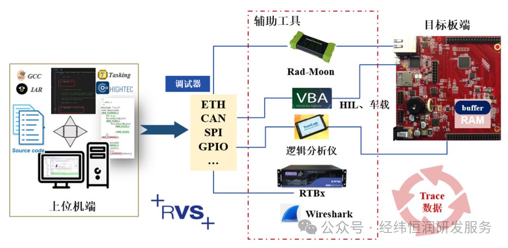
Testing Process Based on RVS
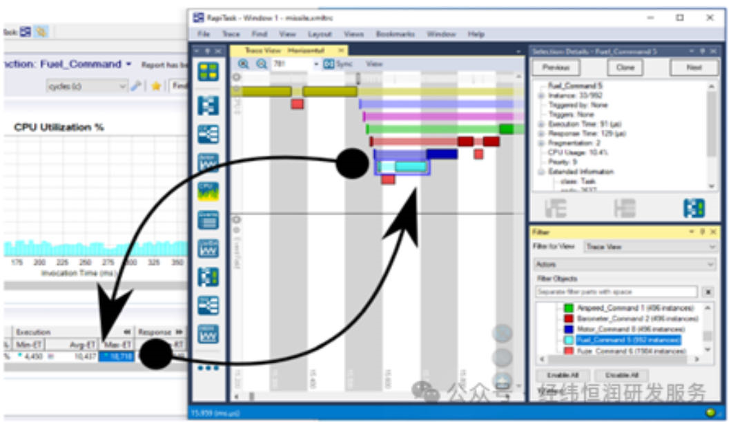
Timing Scheduling Analysis
Pressure Testing Based on Automated Testing Framework
◾ Customer Benefits
-
Ensure that communication, diagnostics, operating systems, IO drivers, network management, and other modules do not pose fatal risks under stress scenarios
-
As a supplement to functional verification, discover potential software quality issues, ensuring software robustness and stability
-
Construct standardized pressure testing case templates to help form testing processes that meet functional safety requirements
-
Test cases are executed using an automated testing framework, facilitating case management and issue tracing
◾ Testing Content
-
Construct stress scenarios for modules such as NVM, IO drivers, CAN, LIN, ETH, COM
-
Analyze the delay characteristics between different system components, verifying the stability of module runtime
-
Verify functional stability under the influence of abnormal injections, high-frequency triggers, bus faults, etc.
-
Verify the effectiveness of core functionalities and the rationality of software responses under extreme conditions
◾ Solution Features
-
Using an automated testing framework to execute test cases, resulting in short testing cycles, high testing efficiency, and strong test reusability
-
Supports software-hardware interaction, monitoring low-level functions, upper-level messages, external signals, etc.
-
Supports testing in PIL/HIL environments, allowing simultaneous injection of various stimuli for testing verification
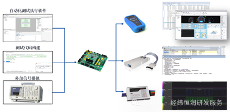
Testing Process Illustration
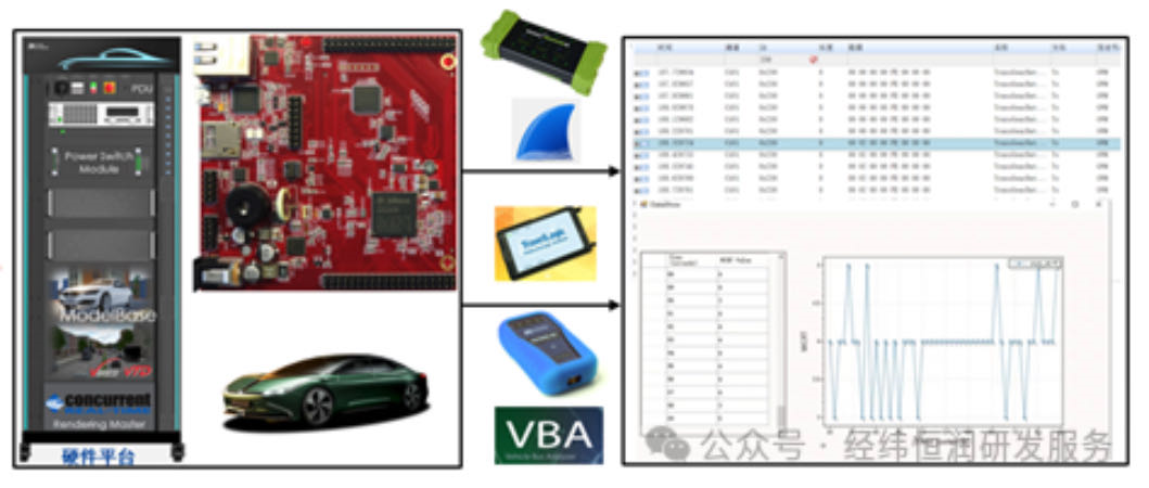
Testing Framework Illustration
Monthly Recommended Plan

Related Course Sections


Click the link above to view the training course outline

Contact Us
Official WeChat|hirain_training
Phone|16619945560
Email|[email protected]