There are input and output circuits on the ECU hardware, while the software consists of programs and data.
The assessment of ECU functionality should focus on these three aspects. Given the numerous pins and functions utilized by the ECU, it is advisable to create a project list and measure each item one by one. Measurement requires observing results; where do we look for results? There are two channels: 1) Alter the sensor signal and directly observe whether the ECU’s output response is valid; 2) Check the diagnostic interface and data stream to see if the ECU has received the input signals from sensors or switches, and whether the displayed data is reasonable; or issue commands to the ECU via the communication port to see if the changes in output control signals are logical. Both methods include a basic check of the ECU program. If you are unsure about the capabilities of the ECU diagnostic tool, the most practical method is to confirm that the input sensor signals are sent to the ECU. If the ECU does not receive them, it can be determined that there is an issue with the internal input circuit; if the expected outputs are not present or the parameters are unreasonable, it can be inferred that there may be a problem with the internal output circuit. This method is fundamental and requires a certain depth of understanding of the circuits and control strategies. It may seem challenging, but the key technical focus of the electrical components in diesel engine electronic control technology lies here; one cannot continue in this field without learning. Of course, the simplest method is to refer to the ECU fault code table, which includes some diagnostics for internal circuits. However, since the ECU is a controller and not a detector, the range of these fault codes is limited.
If the ECU is the heart of the electronically controlled diesel engine, then electricity is the blood of this heart.
Whether in household appliances or industrial electronics, whether in products or system engineering, power supply design is crucial. Even in electrical maintenance, it is common to first check whether the main unit and various circuit parts have normal power supply during repairs. The same applies to diesel engines; to ensure the ECU operates reliably, it is essential to guarantee that the power supplied to the ECU is normal and reliable. If the ECU’s power supply is abnormal, it is like a patient in a coma due to excessive blood loss, causing it to behave erratically and report unreliable fault codes. Without fault codes, it is also untrustworthy. All of this is due to excessive blood loss, with no organic damage to the body, meaning that the ECU’s hardware and software are intact.
Aside from the ECU, based on the relevant information provided by the ECU manufacturer, we know that the working voltage range of the ECU is quite broad. However, abnormal power supply situations can still occur during use. We categorize ECU power supply abnormalities into two main types: overvoltage and undervoltage. Overvoltage is rare in vehicles because the battery itself acts as a very good voltage buffer. As long as the connections are good, most overvoltage energy can be absorbed by it, preventing the power supply voltage from becoming excessively high. On the other hand, undervoltage situations are more complex. The simplest form of undervoltage is a discharged battery. When external electrical components, including the ECU, stop working, the voltage measured across the battery with a multimeter does not represent the battery’s charge, commonly referred to as floating voltage. Once any electrical device operates, especially a large load like a starter motor that draws hundreds of amps, if the battery is discharged, the voltage across the battery terminals can drop significantly. If it falls below the ECU’s minimum operating voltage, the ECU may enter a state of confusion due to blood loss and fail to operate normally. Large current loads also include preheaters, and the inductive energy generated by relay switches can cause momentary voltage drops in the power supply. Such transient voltage anomalies are difficult to capture with a multimeter; if necessary, an oscilloscope may be required. Some decoder models with built-in oscilloscope functions can be useful.
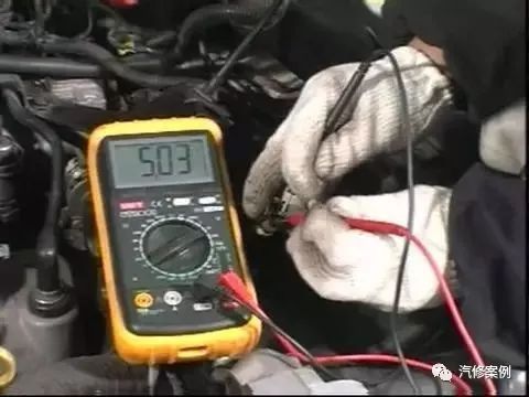
In addition to the ECU, external active sensors also require power supply, which is as important as the ECU’s power supply. The term ‘active’ here refers to those that require a power source. These types of sensors include rail pressure, air pressure, and oil pressure sensors; camshaft and crankshaft speed sensors are active if they have three wires; the accelerator pedal is active; while temperature sensors for oil, air, and water, although they may be integrated with other signals in a single housing, can actually be considered passive, as they do not require an additional independent power line. Even so, it should not be assumed that they cannot operate without power. In fact, within the ECU, a resistor is pulled from the temperature signal line to the internal sensor power supply. This resistor, along with the external temperature sensing resistor, forms a voltage divider circuit. However, this potentiometer does not have a knob; instead, the invisible temperature acts as the knob. When the external temperature sensing resistor is open-circuited, a digital multimeter can be used to measure the voltage between the signal line and the sensor ground. This voltage can be considered equivalent to the internal sensor power supply voltage, yielding the same result as directly connecting the red probe to the positive terminal of the ECU’s internal sensor power supply.
The power supply for various sensors is usually not directly connected to the battery but comes from within the ECU.
Reliable Control Strategy
Inside the ECU, there are several power supply module circuits. These circuits serve to stabilize the voltage, typically at 5V, as sensors convert physical parameters into voltage and require a certain level of precision, making the need for voltage stabilization understandable. Additionally, from the perspective of reliability and safety of the control strategy, the power supplies used by these sensors should not be singular but rather multiple, possibly independent and isolated from each other. Even if they share a common ground, they should have separate wiring externally to prevent signal crosstalk. Furthermore, these power supply module circuits must implement self-protection, allowing the sensor power lines to short-circuit with the sensor ground or chassis ground without damage. Additionally, the ECU must have hardware functionality for detecting and diagnosing these sensor power supplies. If two sensors share a particular sensor power supply, when the power supply for sensor A shorts to ground, causing a voltage drop or loss of power, it will affect the normal operation of sensor B. At this point, the ECU may report a series of fault codes related to sensor B, leading our troubleshooting in the wrong direction, while in fact, sensor B and its circuit are perfectly fine. Therefore, to facilitate future diagnostics, we need to understand the power sharing situation of each electronic control system. The detection method is simple: with the key switch off, use a multimeter in resistance mode to measure which sensor grounds and sensor power pins are interconnected.
In summary, when diagnosing and repairing electronic control systems, the first focus should be on checking the power supply to the ECU and each sensor, which can even serve as a routine check, similar to how one would check for cylinder disconnection during pump calibration. This can help us avoid unnecessary detours and prevent so-called strange faults from arising.
Largest Automotive Repair Case Database
Only Practical Information
Automotive Repair Cases: qixiuanli
Difficult Problems | Timing Adjustment | Automotive Repair Techniques | Maintenance Reset