Translation
Functional Safety of Domain Controller (DC) ECUs
Original: Functional Safety for Domain Controller (DC) ECUs
Translation Review: Lu Ping
➡ (Approximately 3000 words, 10 minutes reading)
01
Functional Safety of Domain Controller (DC) ECUs
In this article, we will explore the following aspects:
• What is a domain controller? Why are OEMs shifting to domain controllers?
• What considerations should we have regarding functional safety in domain controllers?
• What challenges exist when multiple suppliers are involved in the development of domain controllers? How can we address them?
• What is a domain controller? Why are OEMs shifting to domain controllers?
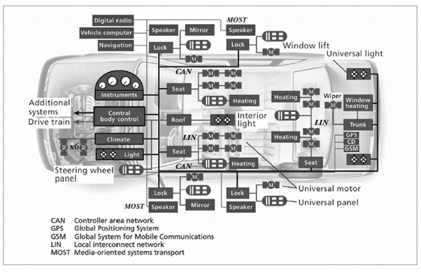
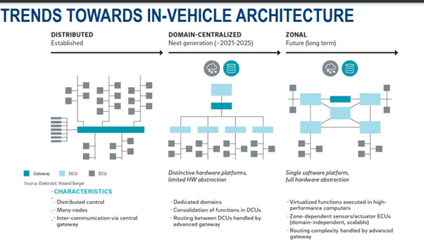
The traditional automotive architecture is decentralized and distributed, with each ECU typically implementing a single feature/function. Each new feature/function adds a new ECU. This architecture is extremely complex and burdensome in terms of wiring (a large number of cables, contacts, fuses, relays, etc.), making it very expensive to layout all ECUs in a vehicle. Furthermore, with the increasing focus on autonomous driving and user experience, vehicles are becoming more software-centric. It is necessary to introduce additional applications or new features/functions with software over-the-air updates without adding or changing hardware. This has prompted automakers to shift to centralized vehicle architectures, where several ECUs related to a single domain are combined into one ECU. Such an architecture significantly simplifies the production logistics process and improves quality. An ECU that integrates multiple functions within a domain is called a domain controller.
Below is a view of a decentralized traditional vehicle architecture. Each box in the diagram represents an ECU.
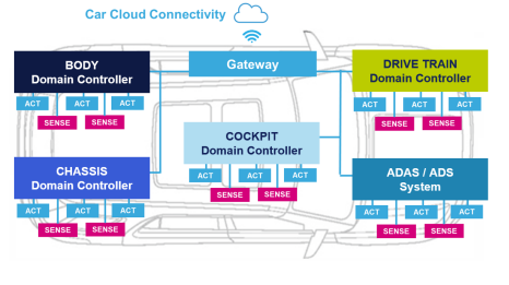
Below is a view of a vehicle architecture based on centralized domain controllers.
Domain controllers with different domains:
a. Infotainment DC (example product)
b. ADAS DC (example product)
c. Powertrain DC (example product)
A DC implements all functions in a system-on-chip (SoC) with multiple cores, providing the required real-time performance and computational power.
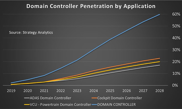
Research predicts that by 2028, the overall penetration rate of domain controllers will approach 60%, despite the lack of collaborative efforts towards domain-based architectures.
From the perspective of ISO26262, a domain controller can be considered as part of several “related items” or several “related items”. For example, an ADAS DC implements various ADAS functions such as ACC, AEB, etc., which can be considered part of the ACC-related items, AEB-related items, etc.
02
What considerations should we have regarding functional safety in domain controllers?
1. DC architecture must be prepared to meet the highest ASIL level requirements
Domain controllers are not fixed in terms of features/functions; they will undergo upgrades, additions, and modifications throughout their lifecycle. From a functional safety perspective, OEMs/Tier 1 should be able to “predict” the highest ASIL level required for the DC. Predictions must be based on potential new features to be added and their required ASIL levels. The hardware and software architecture of the DC should be designed to meet the requirements for achieving this highest ASIL level.
For example, let’s take a cockpit domain controller that currently has an ASIL-A safety target. It has a SoC that meets ASIL-A standards and a software architecture with an ASIL-A operating system and two ASIL-A and QM partitions.
Now, if this DC needs to achieve an ASIL-B safety target in the future, its existing architecture will not support it. The SoC and OS need to be replaced with ASIL-B compliant SoC and OS, and an additional partition for ASIL-B must be created. The hardware design of the DC may also need modifications to meet the required hardware metrics.
In the above example, the architecture of this cockpit DC is not scalable to support new safety targets at higher ASIL levels. This predictive flaw is precisely what must be avoided.
Let’s take another example of an ADAS domain controller that currently supports an ASIL-C architecture and has an ASIL-C camera sensor. If this DC must support an ASIL-D safety target in the future, its existing hardware architecture does not support it. In this case, the DC must either 1) upgrade to an ASIL-D level camera sensor, or 2) perform ASIL decomposition between the camera and another redundant sensor that is at least ASIL-A level, and the architecture of the DC must consider another sensor.
2. Existing safety functions should not be affected by software upgrades
When software upgrades are performed on the road, they should not affect other already qualified safety functions; otherwise, even without any changes in functionality, re-qualification will be required each time, making it an extremely costly affair.
3. Requirements for fault safety, fault degradation, and fault operation for multiple functions
Whether for traditional ECUs or DCs, the principles for implementing fault safety, fault degradation, and fault operation requirements are the same. However, what is interesting for DCs is that several safety functions coexist with various fault safety, fault degradation, and fault operation requirements. Implementing all these functions in a single system is quite interesting.
A fault in one function should not affect another function unless they are related. Otherwise, it will lead to a complete loss of availability for all functions. For example, in an instrument cluster-audio domain DC, if the audio system fails, the instrument cluster should still be able to function and provide the necessary safety notifications and indications to the driver. In an ADAS system, if the lane-keeping assist function fails, it should not affect the performance of the automatic emergency braking function.
The system architecture of the DC should identify faults that will affect each function, and only when these related faults occur should the function be transitioned to a fault-safe/fault-degraded state, rather than any other faults that do not affect the function. For example, if the emergency braking function uses a radar sensor, while the parking assist system uses an ultrasonic sensor, a fault in the ultrasonic sensor will only degrade the parking assist function, while the emergency braking function should remain fully available.
If there is a common fault that spans multiple functions and affects all these functions, such as a CPU fault, this will lead to an overall fault safety condition for all functions.
Fault operation requirements can typically only be achieved through hardware redundancy. For example, a DC can have two independent SoCs performing the same processing, so that even if one fails, the other SoC continues to provide functionality. End-to-end redundancy of features must be considered to achieve fault operation behavior. If the function reads some input from a sensor, redundancy can be implemented in the design with backup sensors in case the primary sensor fails. Two independent CAN channels receiving and sending the same messages and redundant actuators are additional aspects that a DC must consider for fault operation functionality.
03
What challenges exist when multiple suppliers are involved in the development of domain controllers? How can we address them?
It is common for different suppliers to develop different functions of the DC, due to various reasons. One aspect is the complexity of the system and the development work required for a single supplier to develop the entire system. A greater challenge is the knowledge/technical expertise required to develop each function. A single supplier may lack the knowledge and expertise to develop all functions.
Whether for DCs or traditional ECUs, the challenges faced when dealing with suppliers are very similar. However, we emphasize it here because DCs typically have more suppliers involved. This makes it evidently more challenging to obtain the required safety profiles from each supplier and to bring them together to provide a safety case for the entire system.
The first tier is usually the overall responsible party for the safety concept. Tier 1 suppliers must know the requirements for each supplier to gain confidence that the risks in the system have been adequately mitigated.
Typical challenges when dealing with suppliers include:
1. Ambiguity in defining supplier responsibilities.
For example: Suppose a supplier provides complex ICs for the DC, such as microcontrollers or sensors. Should this supplier only provide hardware? Or does the first tier need them to provide any supporting software?
Example 2: If Supplier 1 develops Function 1 and Supplier 2 develops Function 2, who is responsible for ensuring that Function 2 is not interfered with by Function 1? Is it the responsibility of Supplier 1, Supplier 2, or someone else?
2. Assumptions about the ASIL level of hardware/software provided by suppliers.
For example, a supplier claims that their hardware/software supports ASIL-B, or states that they have an ASIL-certified “technical route,” but the first tier assumes that the hardware/software is developed according to ASIL-B.
3. The timeline for suppliers to provide the required ASIL hardware/software does not align with project deadlines.
This is a common issue, not only for safety but even in other areas. In safety cases, it often happens that the hardware/software is functionally ready on time, but the completion of the safety profile is delayed. Therefore, the supplier’s safety profile is not completed before the project deadline.
The uncertainty of supplier responsibilities arises from the lack of clear definitions of roles and responsibilities for each supplier in the DIA. Supplier DIAs are often blindly reused from previous projects without fully considering the challenges and context of the current development project. This must be avoided. If possible, supplier DIAs must be evaluated during the RFQ phase. All real-time challenges must be considered in advance during the implementation of the safety concept. Rather than conducting post-analysis after things go wrong, it is better to conduct pre-analysis at the start of the project to understand what should be considered from the outset to prevent failures.
04
Conclusion
Domain controllers seem poised to dominate in the next decade. However, one drawback of DCs is that many domains may physically span the entire vehicle. Therefore, automakers are also investing in zonal architectures. Zonal architectures address the drawbacks of domain architectures by combining physically close ECUs under a single zonal controller. This brings benefits of reduced wiring and weight—at the cost of increased software complexity. This is because zonal controllers must be able to differentiate traffic between the ECUs connected to them based on functionality.
We will leave you with this image, which provides a simplified view of different architectures.
END