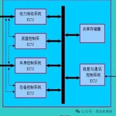
1. Core Fault Analysis of ECU Anomalies
1. Program Corruption: The “Amnesia” of Digital Neurons
-
Typical Triggers:
-
Unofficial ECU tuning (e.g., aggressive first/second-order program flashing leading to checksum failure)
-
CAN bus signal conflicts (devices occupying diagnostic protocol IDs, such as permanent devices on the OBD interface)
-
OTA upgrade interruptions (voltage fluctuations causing packet loss rate > 5%)
-
Failure Symptoms:
-
Loss of throttle baseline learning values
-
Abnormal fuel injection pulse width calculation (deviation > ±15%)
-
False triggering of the anti-theft system (IMEI code not matching BCM)
2. Moisture Damage to Circuit Boards: The “Rheumatism” of Electronic Components
-
Testing Standards:
Test Item Normal Value Fault Determination Insulation Resistance (between layers) >100MΩ <10MΩ Electrolytic Capacitor ESR Value <1Ω >5Ω Oxidation Area of Solder Joints <5% >30% -
High-Risk Areas:
-
Bottom of ECU pins (prone to condensation accumulation)
-
Surroundings of DC-DC conversion module (large fluctuations in operating temperature)
3. Unstable Power Supply Voltage: The “Arrhythmia” of Energy Supply
-
Key Parameters:
-
Steady-state voltage range: 13.5V±0.5V (during engine operation)
-
Instantaneous voltage drop: >9.6V during startup (must be >10.5V for vehicles with start-stop systems)
-
Ripple voltage: <200mV (measured peak-to-peak with an oscilloscope)
2. Symptom Diagnosis and Quick Response
1. Multiple Fault Indicator Warnings (Christmas Tree Phenomenon)
-
Diagnosis Priority:
-
Read freeze frame data (lock the first triggered fault code)
-
Check CAN bus termination resistance (standard 60Ω±2%)
-
Inspect power supply to the gateway module (fuses SB10/SC20)
2. Diagnostic Protocol Failure (Unable to Communicate)
-
Physical Layer Testing:
-
Protocol Layer Testing:
-
K-Line wake-up signal (>7V pulse)
-
ISO-TP frame response time (<100ms)
| Pin | Test Point | Standard Value |
|---|---|---|
| OBD-16 | Power Voltage | 12-14V |
| OBD-6 | CAN-H Voltage | 2.6-2.8V |
| OBD-14 | CAN-L Voltage | 2.2-2.4V |
3. Chaotic Power Output (Random Fluctuations)
-
Data Stream Analysis Focus:
-
Intake pressure sudden changes (>±10kPa/second)
-
Ignition advance angle oscillation (amplitude >±8°)
-
A/F ratio λ value jumps (irregular fluctuations between 0.8-1.2)
3. Systematic Repair Solutions
▌ Phase One: Basic Reset Operations1. Battery Disconnection for Forced Reset
-
Standardized Process:
-
Turn off all vehicle electrical devices (including dash cams)
-
Disconnect negative cable → wait 10 minutes → disconnect positive cable
-
Short-circuit the terminals for 30 seconds (to release residual charge)
-
Reconnect positive terminal first → then negative terminal (torque 4-6N·m)
Notes:
-
Vehicles equipped with intelligent start-stop systems require additional reset of the BSM module
-
High-end models must disable transport mode before disconnection (VAS5054 operation)
▌ Phase Two: ECU Program Refresh1. Device Selection Standards
| Device Type | Applicable Scenario | Refresh Speed |
|---|---|---|
| Original Factory Diagnostic Tool (VAS6154) | Bootloader Repair | Low-speed mode (19.2kbps) |
| Third-party Device (Autel IM608) | Calibration Data Writing | High-speed mode (500kbps) |
| Chip Programmer (PCMFlash) | Low-level Data Repair | Parallel Writing (8 channels) |
2. Flashing Operation Specifications
-
Environmental Requirements:
-
Stable Voltage: Connect to a regulated power supply (13.5V±0.1V)
-
Temperature Control: 20-30℃ (if out of range, use a temperature chamber)
-
Data Verification:
-
Cyclic Redundancy Check (CRC32)
-
Hash Value Comparison (SHA-256)
▌ Phase Three: In-Depth Hardware Inspection1. Circuit Board Repair Process
-
Moisture Treatment:
-
Ultrasonic Cleaning (40kHz, 60℃ pure water)
-
Vacuum Drying (50℃/12 hours, vacuum degree -0.08MPa)
-
Three-proof Paint Spraying (thickness 0.1-0.3mm)
Component-Level Repair:
-
Replace bulging capacitors (low ESR capacitors from the KMQ series)
-
Wire repair for broken connections (0.1mm gold wire bonding)
2. Power System Rectification
-
Main Relay Testing:
Parameter Standard Value Replacement Threshold Pull-in Voltage ≤9V >11V Contact Resistance ≤50mΩ >200mΩ -
Fuse Selection:
-
Main Power Supply for ECU: Slow-blow type (Littelfuse 0SPT series)
-
Sensor Circuit: Fast-blow type (Bussmann ATM series)
4. Preventive Maintenance Strategies
1. Environmental Protection Upgrades
-
Add waterproof ECU protective sleeves (IP69K rating)
-
Install shock-absorbing bases (silicone cushioning pads, shock absorption rate >70%)
2. Power System Reinforcement
-
Parallel supercapacitor modules (16V 300F)
-
Upgrade generator regulators (output fluctuations <±0.3V)
3. Software Health Management
-
Perform full system diagnostic scans monthly (generate health reports)
-
Establish an ECU software fingerprint database (record MD5 values of each version)
5. Classic Fault Case Library
| Case Features | Fault Root Cause | Solution |
|---|---|---|
| ECU failure after water immersion | Pin oxidation causing CAN line short to ground | Replace TE 2280913-1 gold-plated connector |
| Power interruption after xenon light modification | Electromagnetic interference causing ECU restart | Add TDK ZJYS51R5 filter magnetic ring |
| Unable to start after long-term parking | Static current draining battery causing EEPROM data loss | Use XPROG-M to rewrite 93C86 chip |
Technical Summary The essence of ECU control anomalies is a dual failure of “digital-physical,” requiring a layered repair strategy:
-
Software Layer: Retrieve original factory reference data via VIN (force overwrite abnormal parameters)
-
Hardware Layer: Execute three-level circuit testing (visual inspection → thermal imaging → X-ray tomography)
-
System Layer: Rebuild power integrity (ripple suppression ratio >60dB)
It is recommended to equip a dedicated repair platform:
-
ESD workstation (surface resistance 10^6-10^9Ω/sq)
-
Inert gas welding station (nitrogen environment, oxygen content <50ppm)
-
Automatic three-proof paint spraying equipment (thickness accuracy ±0.02mm)
Through systematic maintenance, the failure rate of ECU-related issues can be reduced by 75%, and the stability of the power system can be improved by 40%. For smart vehicles post-2020, it is necessary to additionally monitor OTA upgrade logs to prevent cloud-pushed abnormal program packages from causing systemic risks.
